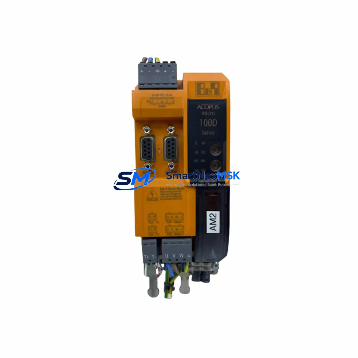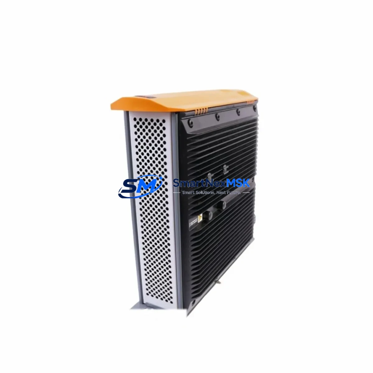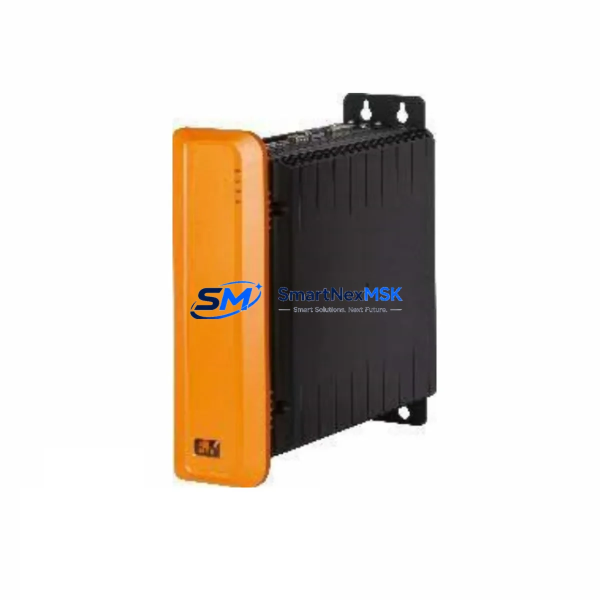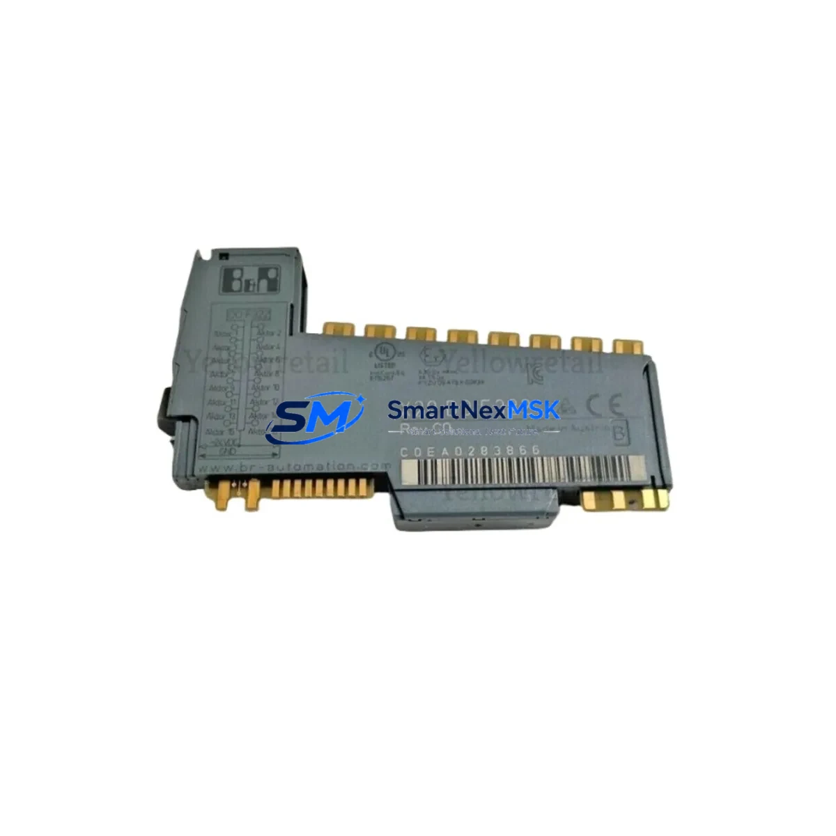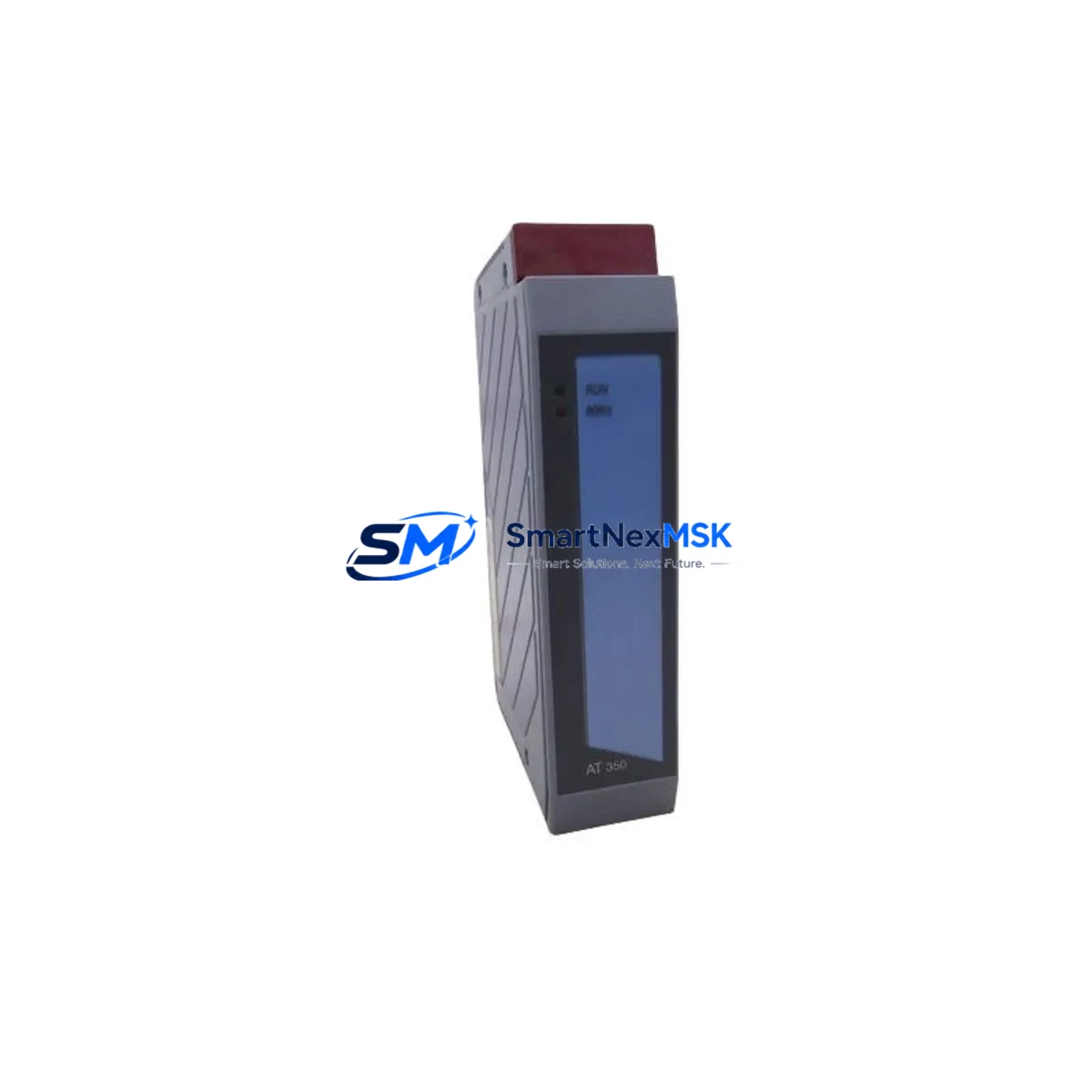
B&R 3AT350.6 Retrofit-Ready RTD Input for AS2000/3000 Control Systems
The B&R 3AT350.6 is a six-channel RTD (Resistance Temperature Detector) input module engineered for the B&R AS2000 and AS3000 programmable controller platforms. As legacy automation lines face increasing pressure from discontinued spare parts and aging infrastructure, the 3AT350.6 has become a critical retrofit component for engineers tasked with extending the operational life of existing control cabinets without full system replacement.
This module accepts Pt100, Pt1000, Ni100, and Ni1000 RTD sensor types across all six channels, providing high-resolution temperature measurement for process control, HVAC, food processing, and precision manufacturing applications. Its backplane-compatible form factor allows direct installation into existing B&R AS2000 and AS3000 racks without mechanical modification, making it the preferred choice for brownfield retrofit projects where minimizing downtime is paramount.
Upgrade Compatibility Table
| Parameter | Details |
|---|---|
| Compatible Platforms | B&R AS2000, AS3000 series |
| Replaces / Upgrades | 3AT350.6 (original), legacy 6-ch RTD variants in AS2000 racks |
| Channel Count | 6 × RTD input channels |
| Supported Sensor Types | Pt100, Pt1000, Ni100, Ni1000 |
| Backplane Interface | AS2000/AS3000 standard backplane bus — no adapter required |
| Terminal Wiring | Compatible with original field wiring; no re-termination required in most installations |
| Module Address | Configured via rotary switch on module face; must match original slot address |
| Communication Protocol | B&R proprietary backplane bus (AS-series) |
| Power Supply Requirement | Supplied via backplane from AS2000/AS3000 power supply module (e.g., 3PS465.9) |
| Installation Type | Direct rack insertion — no tools required |
| Commissioning Note | Verify channel scaling and PLC program tag mapping before live restart |
| Outgoing Test | Each unit function-tested prior to shipment |
| Warranty | 12 months from date of delivery |
Retrofit Planning for Existing Automation Systems
Successful integration of the 3AT350.6 into a running production environment requires careful pre-installation planning. Before pulling the failed or end-of-life module, engineers should document the existing channel configuration using the B&R Automation Studio programming environment, noting all tag names, scaling parameters, and alarm thresholds associated with each RTD channel.
The AS2000 and AS3000 racks typically house a mix of analog and digital I/O modules alongside the RTD input card. Common co-installed components include the 3DI165.6 digital input module, 3DO165.6 digital output module, and 3AO355.6 analog output module — all of which share the same backplane bus and must remain undisturbed during the swap. The rack itself, such as the 3BP150.6 or 3BP250.6 backplane, provides the physical and electrical interface; confirm that the target slot is mechanically sound and that the backplane connector pins are clean and undamaged before insertion.
Power budget verification is essential. The AS2000/AS3000 power supply module — commonly the 3PS465.9 or 3PS565.9 — must have sufficient residual capacity to support the 3AT350.6’s current draw. Review the rack’s total power consumption against the PSU rating before commissioning. If the existing PSU is already near its rated output, consider load redistribution or PSU upgrade as part of the retrofit scope.
For systems that include a B&R 2005 CP or 2010 CP central processing unit communicating over ETHERNET Powerlink or CAN bus, confirm that the CPU firmware version supports the module’s hardware revision. In some older AS2000 installations, a firmware update to the CPU or the use of a 3IF661.6 communication interface module may be required to restore full diagnostic visibility after module replacement.
Field wiring connected to the original 3AT350.6 terminal block should be photographed and labeled before removal. RTD sensors are typically wired in 2-wire, 3-wire, or 4-wire configurations; the replacement module must be configured to match the existing wiring topology to avoid measurement offset errors. If the original installation used 3-wire Pt100 sensors, verify that the compensation resistor jumpers on the new module are set identically to the outgoing unit.
HMI screens built on B&R Power Panel or third-party SCADA systems referencing temperature tags from this module should be validated after restart. Tag addresses are preserved if the module slot address is correctly matched, but a full HMI screen refresh and alarm acknowledgment cycle is recommended before returning the line to automatic operation.
Downtime Control During System Migration
Minimizing unplanned downtime is the primary concern in any live-system module replacement. For the 3AT350.6, the recommended approach is a cold-swap procedure executed during a scheduled maintenance window. Before initiating the swap, place the affected control loop in manual mode at the DCS or PLC level, ensuring that downstream actuators — valves, heaters, or drives — are held at safe states independently of the temperature feedback signal.
Back up the complete PLC project from Automation Studio to a local engineering workstation before any hardware change. This preserves the original program logic, I/O configuration, and communication settings, providing a recovery baseline if the replacement module requires re-parameterization. The backup process typically takes under five minutes and eliminates the risk of configuration loss during the swap.
Physical replacement of the 3AT350.6 is a tool-free operation: release the module locking lever, withdraw the old card, insert the replacement into the same slot, and engage the locking lever until it clicks. Reconnect the field wiring terminal block — which is typically a plug-in connector that can be transferred directly from the old module to the new one without disturbing individual wire terminations. This plug-and-play terminal design is one of the key advantages of the AS2000/AS3000 platform for retrofit work, as it eliminates re-wiring errors and reduces swap time to under ten minutes in most cases.
After power-up, monitor the CPU status LEDs and the module’s channel status indicators. All six channels should report valid readings within the first scan cycle. If any channel shows an error, verify the RTD sensor connection, check the wiring configuration jumpers, and confirm that the module address switch matches the original slot assignment. Once all channels are confirmed healthy, return the control loop to automatic mode and observe the process variable trend for at least one full control cycle before leaving the panel unattended.
Retrofit Support FAQ
Q1: Is the B&R 3AT350.6 a direct drop-in replacement for the original module in AS2000 and AS3000 racks?
Yes. The 3AT350.6 uses the standard AS2000/AS3000 backplane connector and occupies a single rack slot. No mechanical adapters or wiring changes are required in the vast majority of installations. Confirm the module address switch setting matches the original before power-up.
Q2: What commissioning steps are required after installing the replacement module?
Set the rotary address switch to match the original slot address, reconnect the field wiring terminal block, and power up the rack. In Automation Studio, perform an online connection to the CPU and verify that all six RTD channels report valid process values. Check channel scaling, engineering unit conversion, and alarm limits against the backed-up project configuration. No program download is required if the module type and address are unchanged.
Q3: Can this module be used in systems that have been partially migrated to a newer B&R X20 or X67 platform?
The 3AT350.6 is designed exclusively for the AS2000/AS3000 backplane architecture and is not directly compatible with the X20 or X67 I/O bus. In hybrid migration projects where legacy AS-series racks coexist with newer X20 islands, the 3AT350.6 continues to serve the legacy rack while X20 AI modules handle new I/O points. Full migration to X20 would require replacing the RTD inputs with an equivalent X20 analog input module and remapping the associated PLC tags.
Q4: What does the 12-month warranty cover, and how is it handled?
The 12-month warranty covers manufacturing defects and functional failures under normal operating conditions from the date of delivery. Each unit undergoes functional testing prior to shipment. In the event of a warranty claim, contact our sales team with the order reference and a description of the fault. We will arrange priority replacement dispatch to minimize your production downtime.
© 2026 SMARTNEXMSK. All rights reserved.
Original Source: https://smartnexmsk.com
Contact: [email protected] | +86 18259474341