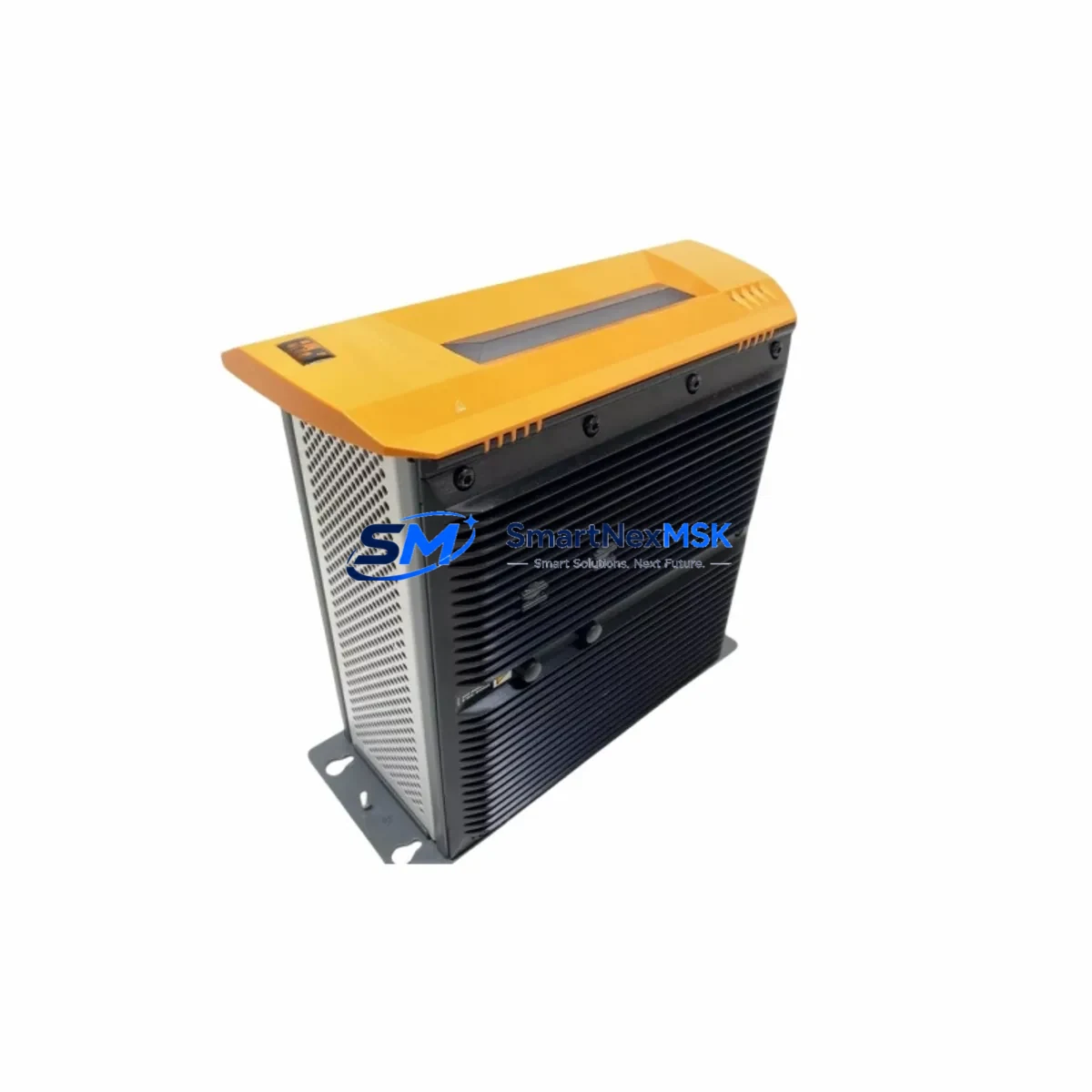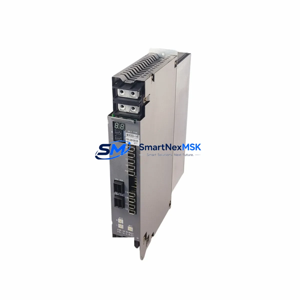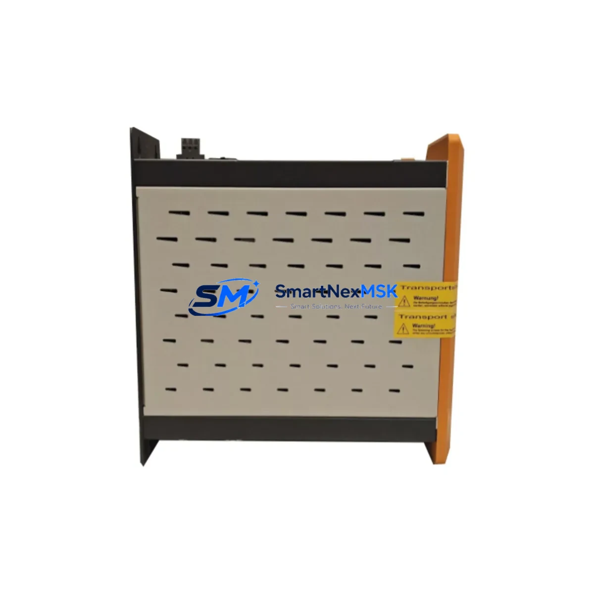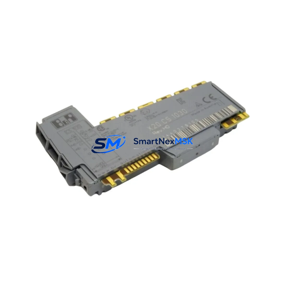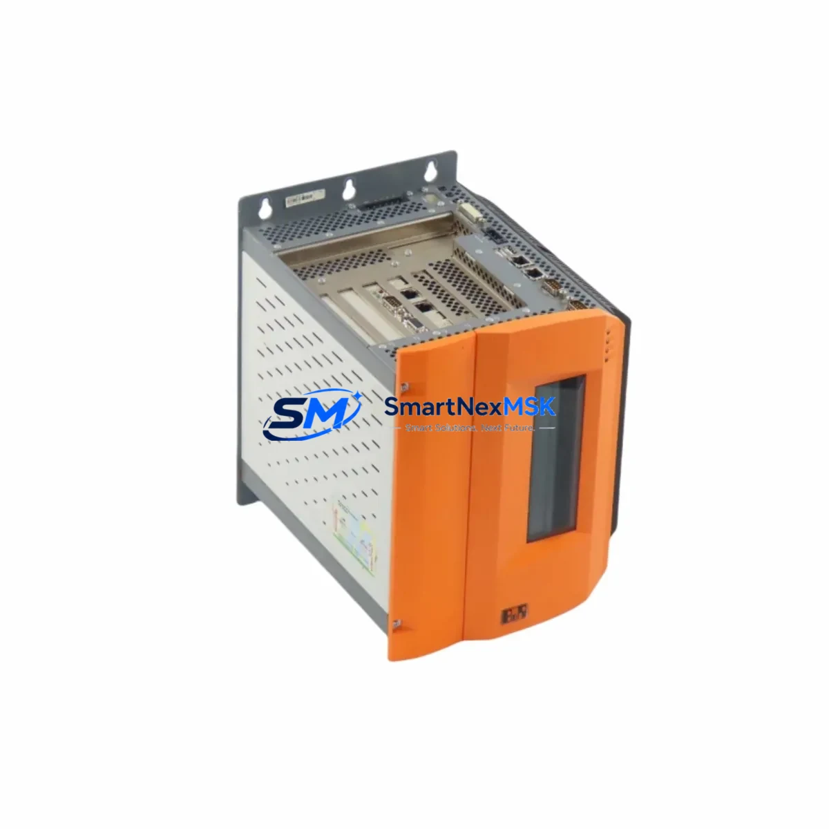
B&R 5PC600.SX05-01 Retrofit-Ready Panel PC for APC620 Control Systems
The B&R 5PC600.SX05-01 is a high-performance industrial panel PC engineered for seamless integration into existing Automation PC 620 (APC620) control architectures. Whether you are replacing an end-of-life unit, upgrading a legacy production line, or recovering a critical control cabinet after an unplanned failure, the 5PC600.SX05-01 delivers the electrical, mechanical, and software compatibility required to restore operations with minimal disruption.
Designed for demanding industrial environments, this unit supports the full B&R Automation Studio programming environment, ensuring that existing PLC logic, HMI screen layouts, and communication configurations can be migrated or reused without ground-up reprogramming. For facilities running mixed-generation B&R hardware — including legacy 5PC600.SX02-00 or 5PC600.SX04-00 variants — the 5PC600.SX05-01 provides a validated upgrade path that preserves investment in existing control infrastructure.
Upgrade Compatibility Table
| Parameter | Legacy Unit (e.g. 5PC600.SX02-00) | 5PC600.SX05-01 (This Unit) | Retrofit Notes |
|---|---|---|---|
| Form Factor | APC620 Compact Chassis | APC620 Compact Chassis | Direct panel cutout fit; no mechanical modification required |
| CPU Architecture | Intel Celeron / Pentium M | Intel Atom / Core i-series (variant dependent) | Verify Automation Studio project compatibility before migration |
| Backplane Interface | B&R IF-series backplane connector | B&R IF-series backplane connector | Compatible with existing X20 and X67 I/O backplane assemblies |
| Communication Protocols | POWERLINK, Modbus TCP, CANopen | POWERLINK, Modbus TCP, CANopen, OPC UA | OPC UA is additive; existing POWERLINK network topology unchanged |
| Power Supply Requirement | 24 VDC, ~40 W typical | 24 VDC, ~55 W typical | Verify existing X20PS9400 or equivalent PSU capacity before swap |
| HMI Display Interface | Integrated TFT, DVI-D optional | Integrated TFT, DVI-D / DisplayPort optional | Existing HMI screen wiring and mapp View projects are reusable |
| Installation Requirement | DIN rail or panel mount | DIN rail or panel mount | Existing mounting hardware retained |
| Warranty | — | 12-Month Warranty | Covers hardware defects; includes pre-shipment functional test |
Retrofit Planning for Existing Automation Systems
A successful retrofit of the 5PC600.SX05-01 into an operating production environment requires systematic pre-migration planning. Before powering down the control cabinet, engineers should document the existing terminal wiring layout, confirm the 24 VDC supply rail capacity — particularly if the cabinet also powers an X20PS9402 redundant power supply module or a 5AC901.HDDI-01 hard disk drive interface — and photograph all connector positions on the backplane.
The backplane itself — typically a 5PC600.BP00-01 or 5PC600.BP02-00 passive backplane — does not require replacement in most APC620 retrofit scenarios. The 5PC600.SX05-01 slides into the same CPU slot and locks with the standard retention mechanism. However, if the existing backplane carries a 5PC600.ETH1-01 Ethernet interface card or a 5PC600.SX00-00 legacy CPU module, the slot assignment and module address configuration in Automation Studio must be reviewed and updated to reflect the new hardware revision.
For systems that include X20AI4622 analog input modules or X20DI9371 digital input modules connected via the X2X Link bus, the I/O configuration in the existing Automation Studio project will remain valid provided the module addresses are preserved. Engineers should export the full hardware configuration tree before the swap and compare it against the new CPU’s auto-detected topology after first boot.
Communication links to upstream SCADA systems or MES platforms — whether via POWERLINK, Modbus TCP, or OPC UA — should be tested in isolation before returning the line to production. If the existing control cabinet includes a 5ACPCI.ETH1-01 PCI Ethernet card for legacy fieldbus bridging, verify that the new CPU’s PCI slot mapping matches the driver assignment in the Automation Studio configuration. Programming cables such as the 5CASDL.0018-00 SDL cable or a standard USB-to-B&R interface adapter will be required for initial commissioning and firmware verification.
Downtime Control During System Migration
Minimizing unplanned downtime is the primary operational concern during any APC620 panel PC replacement. The recommended approach is to prepare the 5PC600.SX05-01 as a pre-configured hot-spare: load the existing Automation Studio project onto the replacement unit in a bench environment, verify that all I/O channel assignments, POWERLINK node numbers, and HMI mapp View runtime configurations are correct, and perform a full functional simulation before the scheduled maintenance window.
During the physical swap, the control cabinet should be de-energized at the main isolator. The existing CPU module is removed by releasing the backplane retention latch — no tools are required. The 5PC600.SX05-01 is inserted into the same slot, the backplane connector engages, and the retention latch is re-secured. Terminal wiring on the front-panel I/O connectors is reconnected according to the pre-documented layout. Total physical swap time for a trained technician is typically under 20 minutes.
After power-up, Automation Studio’s online connection should be used to verify that the CPU has correctly enumerated all backplane modules, that the POWERLINK network has achieved operational state, and that all HMI screens are rendering correctly. If the system includes a 5PC600.SX05-00 or earlier CPU with a different firmware baseline, a firmware update via the B&R Automation Studio upgrade wizard may be required before the project transfer. Original program logic, PID loop parameters, and safety interlock configurations are preserved in the project file and are not affected by the hardware swap.
Retrofit Support FAQ
Q1: Is the 5PC600.SX05-01 a direct drop-in replacement for the 5PC600.SX02-00 and 5PC600.SX04-00?
Yes. The 5PC600.SX05-01 uses the same APC620 compact chassis form factor and B&R IF-series backplane connector. It installs into the same CPU slot without mechanical modification. The Automation Studio project must be re-compiled for the new CPU hardware revision, but existing I/O configurations, HMI layouts, and communication settings are fully reusable.
Q2: What wiring changes are required during the retrofit?
In most cases, no wiring changes are required. The 24 VDC power input terminals, USB ports, and Ethernet connectors are in the same physical positions as the legacy APC620 CPU variants. If the existing cabinet uses a 5PC600.ETH1-01 Ethernet interface card, verify that the MAC address and IP assignment in the SCADA or MES system are updated to reflect the new unit’s network identity.
Q3: How is compatibility with existing POWERLINK and Modbus TCP networks verified?
After installation, use Automation Studio’s online diagnostic view to confirm that all POWERLINK nodes — including any X20DI9371 or X20AI4622 remote I/O modules — have achieved operational status. Modbus TCP connections should be tested by polling the existing register map from the SCADA system. OPC UA server configuration, if newly enabled on the 5PC600.SX05-01, should be validated against the client subscription list before going live.
Q4: What does the 12-month warranty cover, and is pre-shipment testing performed?
Every 5PC600.SX05-01 unit shipped by SMARTNEXMSK undergoes a pre-shipment functional test covering power-on self-test, backplane interface verification, and communication port validation. The 12-month warranty covers hardware defects in materials and workmanship from the date of shipment. Units are shipped with full ESD protection packaging and are accompanied by a test report on request.
© 2026 SMARTNEXMSK. All rights reserved.
Original Source: https://smartnexmsk.com
Contact: [email protected] | +86 18259474341