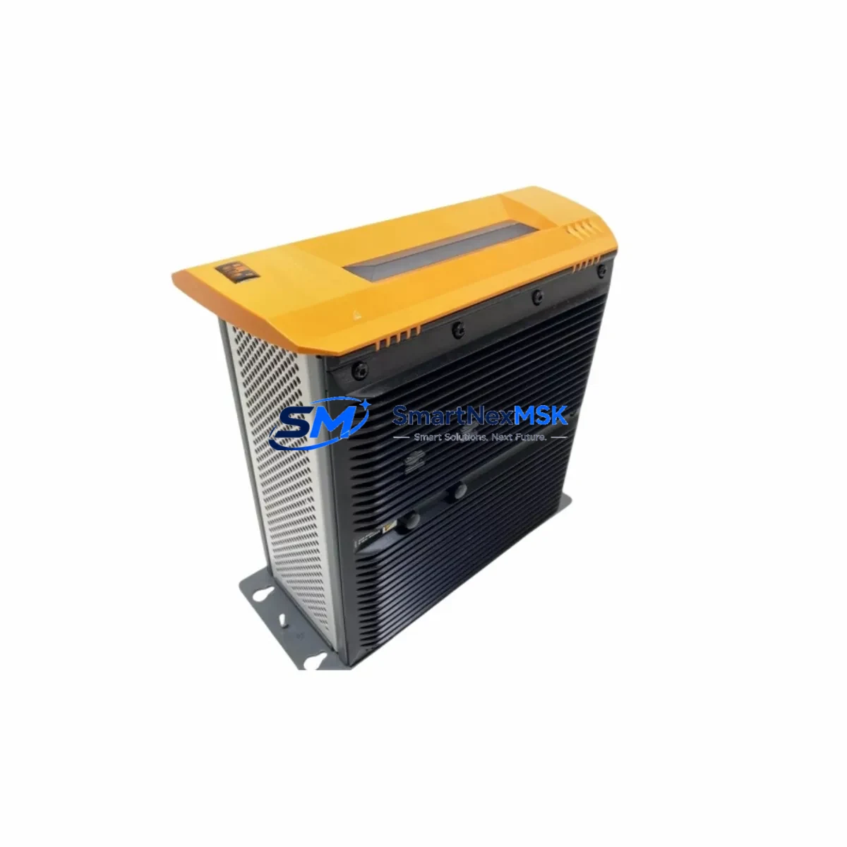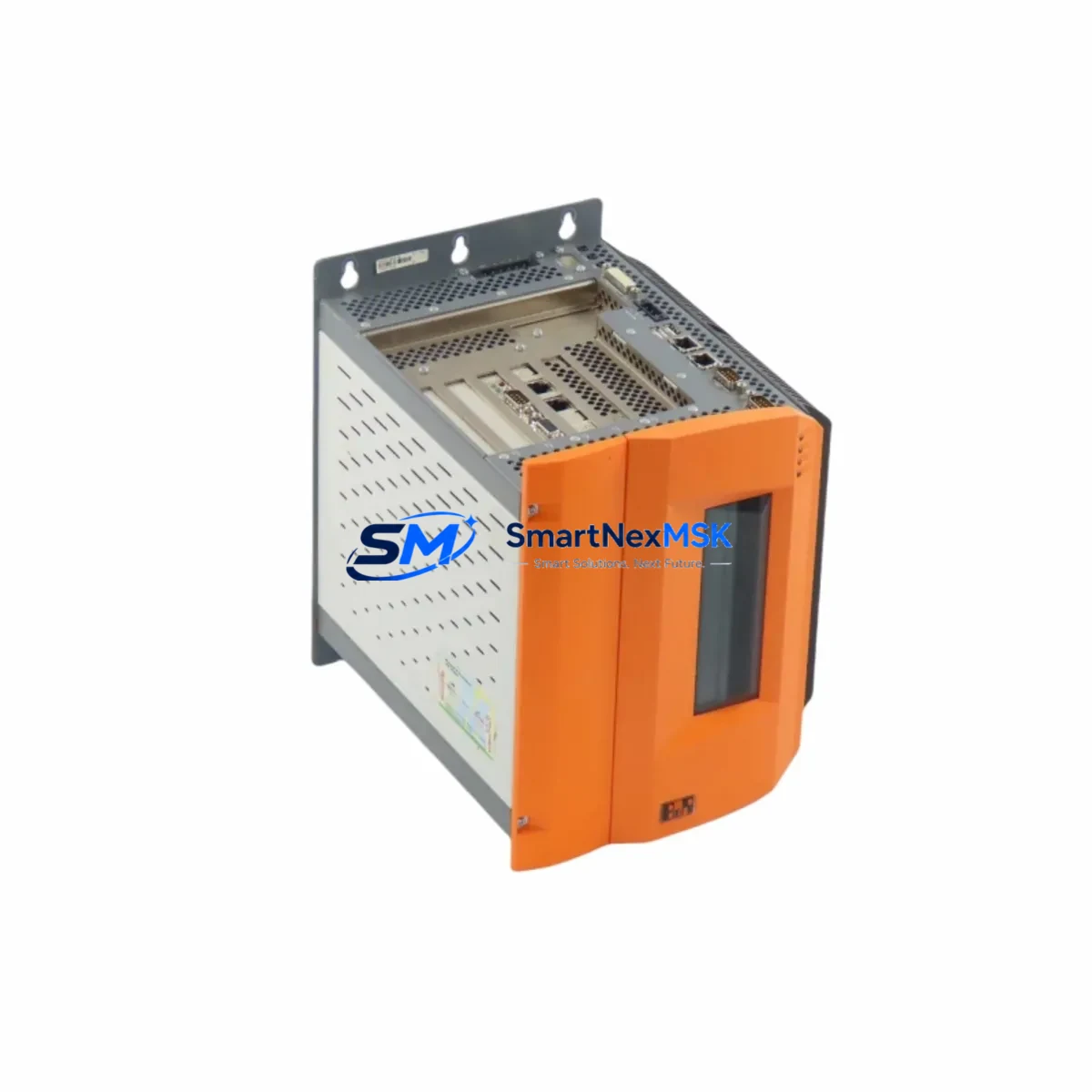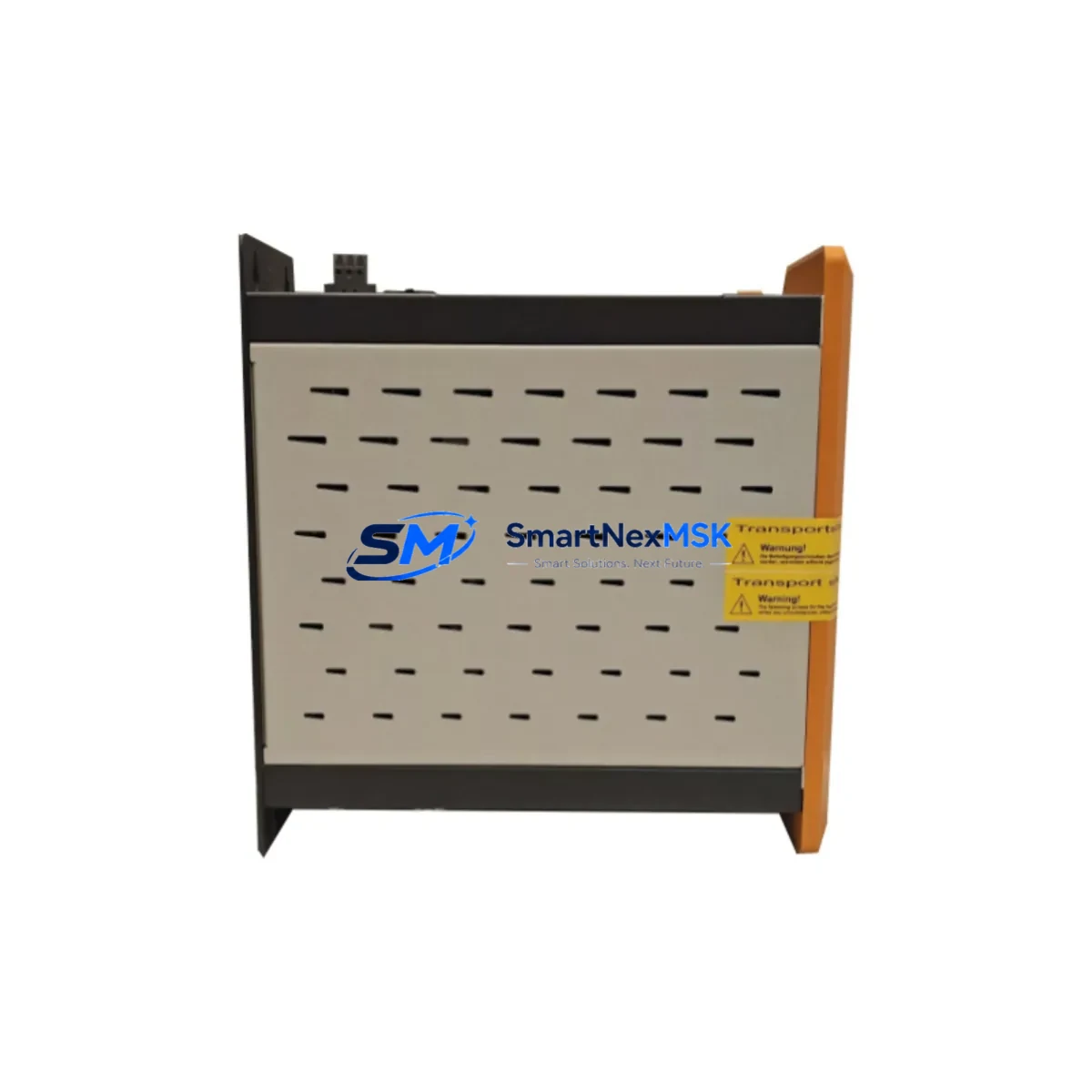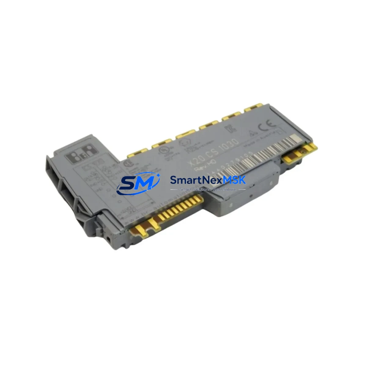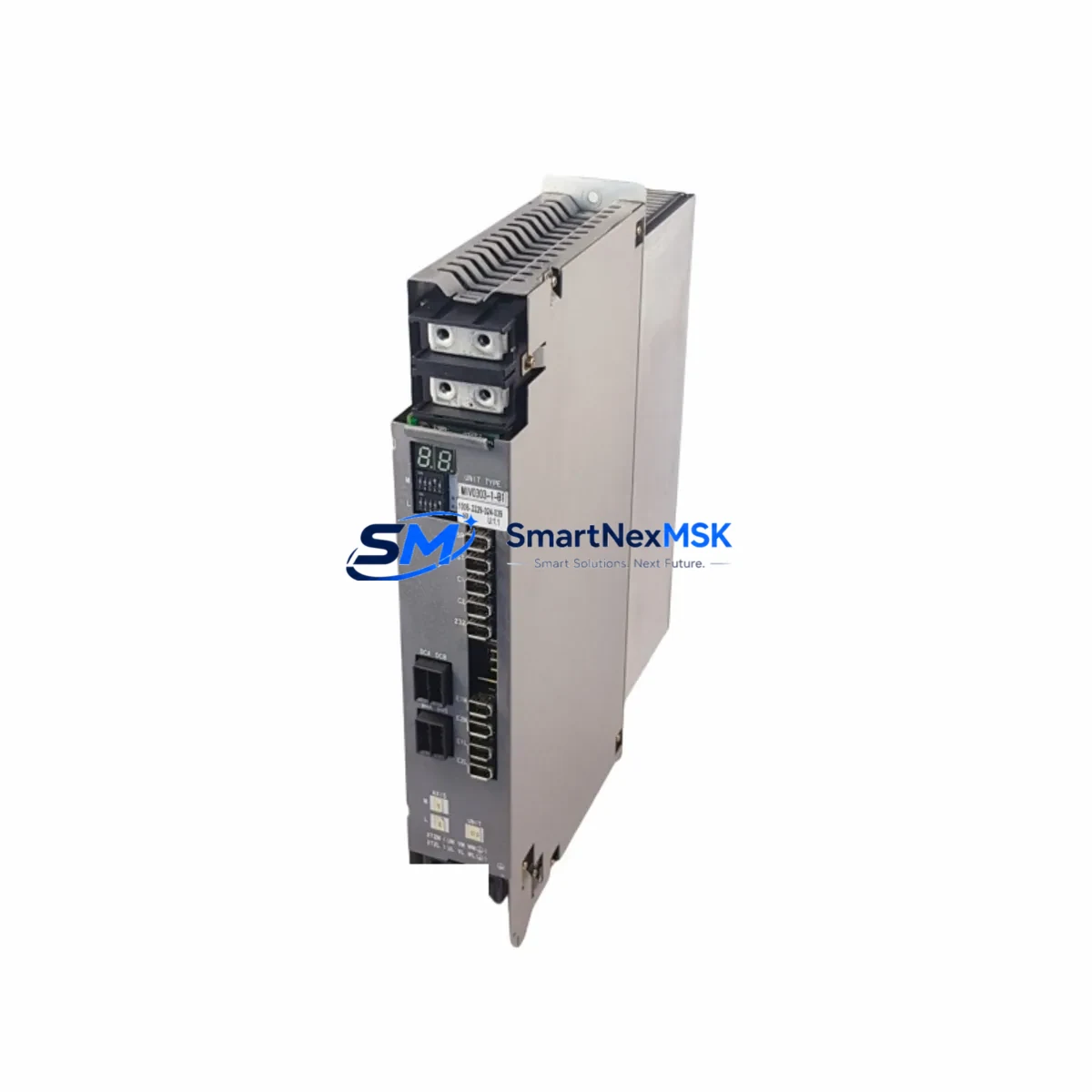
B&R 5PC810.SX01-P00 Retrofit-Ready Panel PC for APC810 Control Systems
The B&R 5PC810.SX01-P00 is a fanless, compact industrial panel PC engineered for seamless integration into existing APC810-series control architectures. Whether you are replacing an end-of-life unit, upgrading a legacy automation cabinet, or migrating a production line from an older B&R platform, the 5PC810.SX01-P00 delivers the processing performance, I/O compatibility, and communication flexibility required for modern industrial environments — without forcing a full system redesign.
This module is widely deployed as a direct retrofit replacement for discontinued APC810 variants across automotive assembly, food processing, packaging, and discrete manufacturing facilities. Its compact form factor, passive cooling design, and standardized backplane interface make it a preferred choice for system integrators managing multi-site upgrades with strict downtime budgets.
Upgrade Compatibility Table
| Parameter | Detail |
|---|---|
| SKU / Part Number | 5PC810.SX01-P00 |
| Brand / Manufacturer | B&R Industrial Automation |
| Series | APC810 |
| Form Factor | Compact Fanless Panel PC |
| Backplane Interface | APC810-compatible IF slot (compatible with 5AC801.SDSS-00, 5AC801.SDSS-01 expansion slots) |
| Communication Compatibility | POWERLINK, CAN, RS232/RS422/RS485, Ethernet (compatible with X20 and X67 I/O networks) |
| Replacement Candidates | 5PC810.SX00-P00, 5PC810.SX02-P00, legacy APC620 panel PC variants |
| Installation Requirement | DIN rail or panel mount; verify cabinet cutout dimensions before installation |
| Wiring Adaptation | Terminal block pinout compatible with standard APC810 wiring harness; verify 24 VDC supply capacity ≥ 60 W |
| Debugging Focus | Module address reassignment in Automation Studio; HMI screen re-mapping if upgrading from APC620 |
| Warranty | 12-Month Warranty — covers hardware defects, DOA replacement, and functional verification |
Retrofit Planning for Existing Automation Systems
Successful deployment of the 5PC810.SX01-P00 in a retrofit scenario begins with a thorough audit of the existing control cabinet. Engineers should first verify the available 24 VDC power supply capacity — the 5PC810.SX01-P00 requires a stable supply with sufficient headroom to support connected expansion modules. If the existing 5AC801.PDSS-00 power supply module is undersized, it should be upgraded concurrently to avoid instability under full load.
Terminal wiring from the legacy unit can typically be transferred directly, but technicians should cross-reference the terminal block layout against the current wiring diagram. Where the original installation used a 5CASDL.0xxx-00 SDL cable for display connection, the same cable standard is retained on the 5PC810.SX01-P00, simplifying panel display continuity. If the existing HMI panel is a 5AP920.1505-01 or similar APC810-generation display, no display adapter is required.
For systems running X20 distributed I/O — such as X20CP1586 or X20CP3586 CPUs connected via POWERLINK — the 5PC810.SX01-P00 integrates without protocol changes. The POWERLINK network address and node configuration stored in the existing Automation Studio project remain valid, provided the replacement unit is configured with the same station number. Engineers should export and archive the full Automation Studio project before beginning hardware replacement.
Where the legacy system used 5AC801.SDSS-00 CompactFlash or SSD storage modules, these can be transferred to the replacement unit if the slot configuration matches. Verify the storage module firmware version is compatible with the target Automation Runtime version before transfer. In cases where the original system used a 5AC801.CANI-00 CAN interface module for fieldbus communication, the same module can be re-seated in the new backplane without reconfiguration.
Systems that previously relied on a 5AC801.RSIS-00 RS232/RS422 interface for serial communication with third-party drives, barcode readers, or weighing systems should verify that the serial port parameters (baud rate, parity, stop bits) are preserved in the replacement project. This is particularly important in lines where the panel PC communicates with legacy ACOPOS servo drives via RS232 before a POWERLINK migration is completed.
Before powering up the retrofitted cabinet, confirm that the backplane slot assignments match the original hardware configuration. Mismatched slot addresses are the most common cause of startup faults in APC810 retrofit projects and can be resolved quickly in Automation Studio’s hardware configuration view.
Downtime Control During System Migration
Minimizing production downtime during a panel PC replacement requires preparation that begins well before the maintenance window. The recommended approach is to pre-configure the 5PC810.SX01-P00 offline using a bench test setup — install the Automation Runtime, load the archived project, and verify all I/O mappings and communication links before the unit reaches the production floor.
Where the original system used a 5AC801.SDSS-01 SSD module with a cloneable image, a direct image transfer to the replacement unit’s storage module can reduce on-site configuration time to under 30 minutes. For systems without a stored image, the Automation Studio project should be compiled and transferred via USB or Ethernet prior to the maintenance window.
During the physical swap, the existing wiring harness, SDL display cable, and expansion modules can remain in place. Only the core panel PC unit is removed and replaced. After seating the 5PC810.SX01-P00, restore power, confirm the POWERLINK network initializes correctly, verify all X20 I/O nodes report online, and perform a controlled program start. HMI screens should be validated against the original operator interface to confirm all process values, alarm pages, and trend displays are rendering correctly before releasing the line to production.
For critical processes, a parallel run strategy — where the replacement unit is validated on a secondary test rack before the live swap — is strongly recommended. This approach eliminates the risk of unexpected program incompatibilities and ensures the 12-month warranty period begins from a verified, fully functional baseline.
Retrofit Support FAQ
Q1: Is the 5PC810.SX01-P00 a direct drop-in replacement for the 5PC810.SX00-P00?
In most installations, yes. The backplane interface, power connector, and SDL display port are physically compatible. However, verify the processor performance tier matches your application’s cycle time requirements, as the SX01 and SX00 variants differ in CPU specification. Automation Studio project recompilation is recommended after replacement.
Q2: Can I reuse my existing wiring and terminal blocks?
Yes. The 5PC810.SX01-P00 uses the same terminal block standard as other APC810-series units. Existing wiring harnesses, including 24 VDC power, SDL display cables, and USB peripherals, are directly compatible. Always verify supply voltage and current capacity before powering up.
Q3: What pre-shipment testing is performed?
Each unit undergoes power-on functional verification, backplane interface testing, and communication port validation before dispatch. Units are shipped with a test report. The 12-month warranty covers hardware defects identified after installation, with DOA replacement processed within 5 business days of confirmed fault diagnosis.
Q4: How do I handle HMI screen remapping after replacement?
If replacing a unit within the same APC810 generation, HMI screens created in Automation Studio’s mapp View or VC4 environment require no remapping — the display resolution and touch interface parameters are identical. If migrating from an APC620-generation panel PC, screen layouts may require adjustment to match the updated display resolution. Our technical team can provide pre-sales compatibility guidance upon request.
© 2026 SMARTNEXMSK. All rights reserved.
Original Source: https://smartnexmsk.com
Contact: [email protected] | +86 18259474341