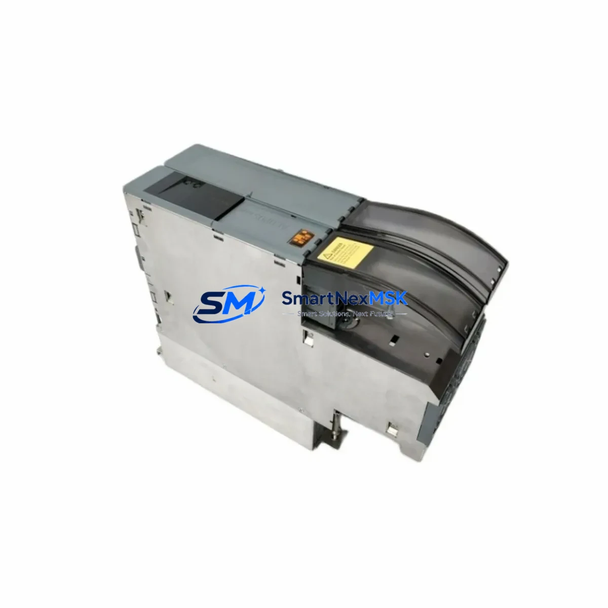
B&R 8BOP0220HC00.001-1 Maintenance-Ready Spare for ACOPOS Automation
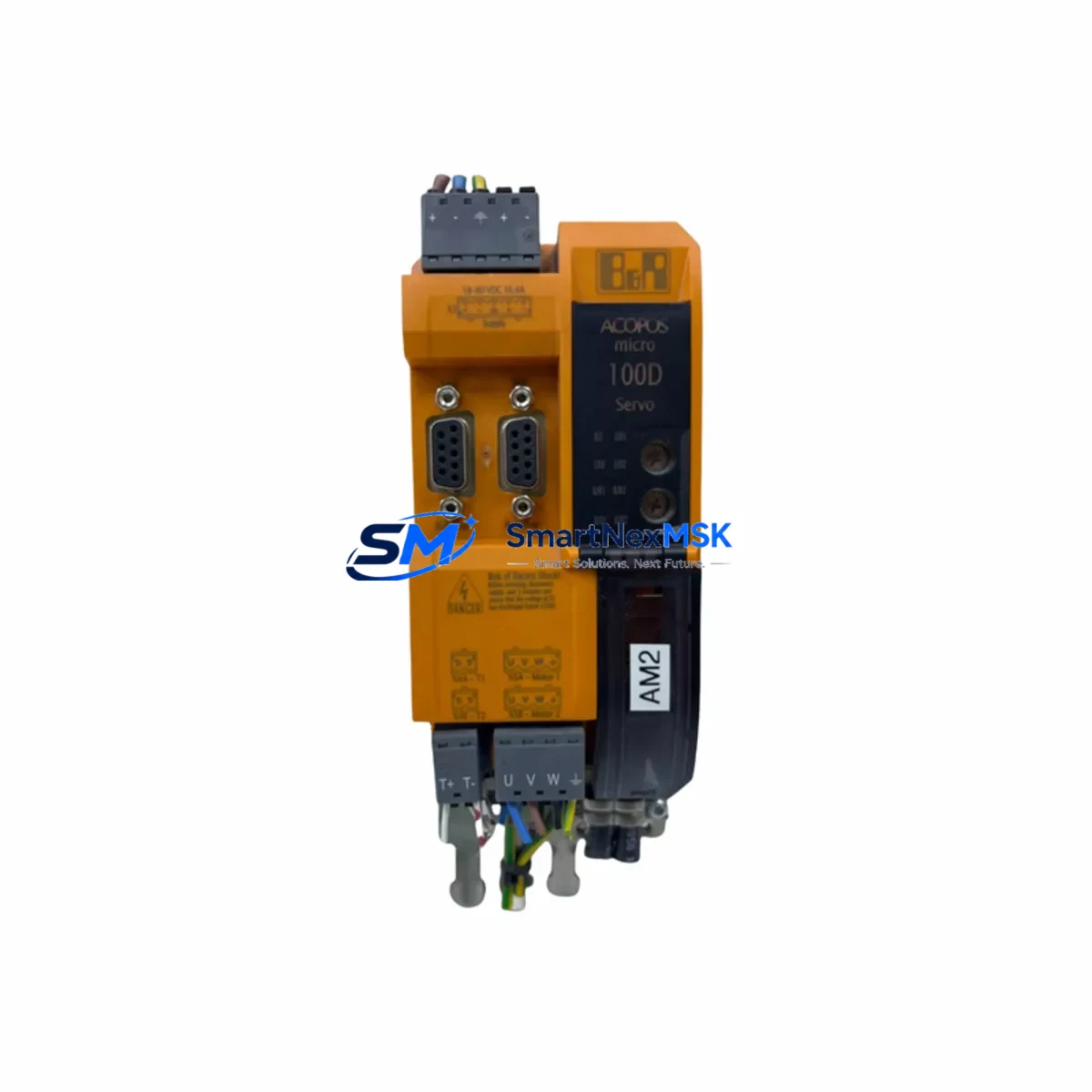
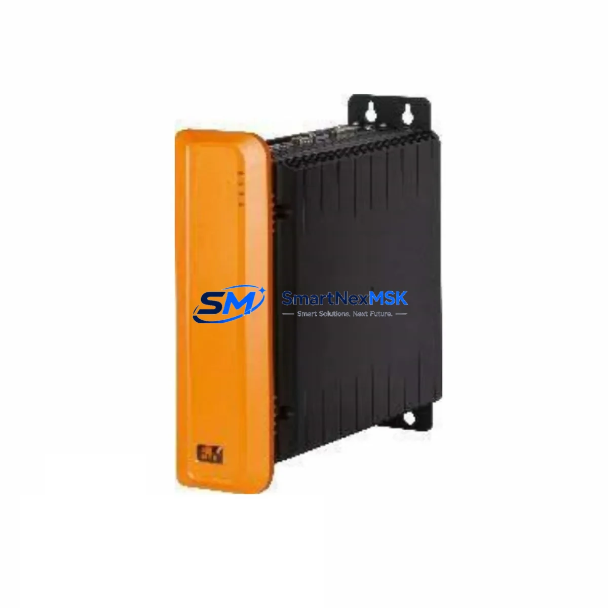
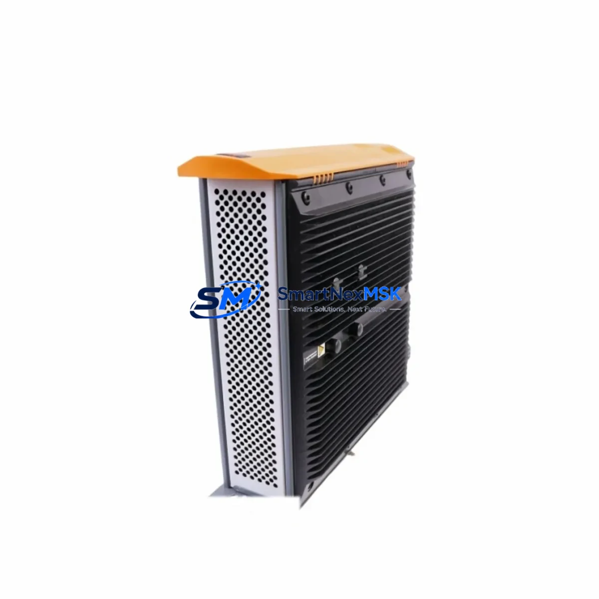
The B&R 8BOP0220HC00.001-1 is an original DC Bus Power Supply module designed for the ACOPOS servo drive platform. Rated at 22 A continuous DC bus output, this module serves as the centralized power backbone for multi-axis ACOPOS drive configurations. For maintenance engineers managing aging servo systems, having a verified spare of the 8BOP0220HC00.001-1 on hand is one of the most effective strategies to eliminate unplanned downtime caused by power supply degradation or sudden failure.
In industrial environments where ACOPOS drives control precision motion — packaging lines, press feeders, winding machines, or CNC transfer systems — a failed DC bus power supply can halt an entire production cell. The 8BOP0220HC00.001-1 is a direct replacement that restores system operation without requiring firmware changes, drive reconfiguration, or HMI screen remapping. Its plug-and-play compatibility with the ACOPOS backplane makes it a preferred choice for both planned maintenance cycles and emergency breakdown recovery.
Spare Maintenance Table
| Parameter | Specification / Detail |
|---|---|
| SKU / Part Number | 8BOP0220HC00.001-1 |
| Brand | B&R (Bernecker + Rainer) |
| Series | ACOPOS Servo Drive System |
| Module Type | DC Bus Power Supply Module |
| Rated Output Current | 22 A (DC Bus) |
| Mounting Interface | ACOPOS Backplane / Rail Mount |
| Communication Compatibility | POWERLINK, CAN, compatible with B&R Automation Studio |
| Replacement Compatibility | Direct drop-in for ACOPOS multi-axis configurations |
| Installation Requirement | No firmware update required; matches original backplane pinout |
| Application Environment | Industrial servo motion control, packaging, press, CNC |
| Maintenance Recommendation | Inspect DC bus capacitors and cooling airflow annually |
| Origin | Austria |
| Warranty | 12-Month Warranty |
Maintenance Planning for Continuous Operation
When scheduling preventive maintenance around the 8BOP0220HC00.001-1, experienced maintenance engineers know that the DC bus power supply does not operate in isolation. A comprehensive inspection of the surrounding ACOPOS system components is essential to prevent cascading failures after a power supply replacement.
Start by verifying the condition of the ACOPOS servo drive modules (such as the 8V1090.00-2 or 8V1180.00-2) that draw power from the DC bus. A degraded power supply often causes subtle voltage ripple that accelerates capacitor wear in adjacent drive modules. Inspect the ACOPOS backplane connector contacts for oxidation or heat discoloration — the backplane carries both power and POWERLINK communication signals, and any contact resistance will affect both power delivery and real-time network timing.
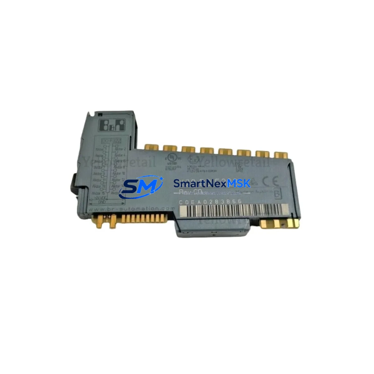
Check the B&R X20 I/O modules connected to the control system. In many ACOPOS installations, the X20 system handles digital and analog I/O for position feedback, safety interlocks, and process signals. A power event that damages the 8BOP0220HC00.001-1 may also have caused transient stress on nearby X20 power supply modules (e.g., X20PS9400 or X20PS9402). These should be tested under load before returning the system to production.
Inspect the POWERLINK network cables and managed switches in the control cabinet. ACOPOS drives rely on POWERLINK for deterministic real-time communication with the B&R PLC (such as the X20CP series controller). A loose or damaged POWERLINK cable can cause axis synchronization errors that are often misdiagnosed as drive faults. While the cabinet is open, also verify the 24 VDC auxiliary power supply feeding the control logic — a failing auxiliary supply is a common secondary cause of ACOPOS fault codes that appear after a DC bus power supply replacement.
For systems using B&R ACOPOS encoder interface modules (such as the 8AC114.60-1 or 8AC122.60-1), confirm that encoder signal integrity is maintained after the power supply swap. Encoder feedback errors post-replacement are typically caused by ground potential shifts introduced during the maintenance procedure. Finally, check the motor power cables and braking resistor connections — the braking resistor dissipates regenerative energy during deceleration, and a failed resistor or loose terminal can cause DC bus overvoltage faults that damage a newly installed power supply module.
Site Replacement Workflow
Replacing the 8BOP0220HC00.001-1 on-site follows a structured sequence to minimize downtime and protect the surrounding ACOPOS system:
Step 1 — Safe Isolation: Disable the main contactor and allow the DC bus capacitors to fully discharge (minimum 5 minutes after power-off, or verify with a DC voltmeter that bus voltage is below 50 V). Do not rely solely on the drive’s ready LED as a discharge indicator.
Step 2 — Document Current Configuration: Before removal, photograph the terminal wiring, note the module slot position on the backplane, and record any active fault codes from the B&R Automation Studio diagnostics screen. This documentation is critical if the replacement module requires any address or parameter verification.
Step 3 — Module Swap: Remove the 8BOP0220HC00.001-1 by releasing the backplane locking mechanism. Insert the replacement module into the same slot. Verify that the backplane connector is fully seated — partial engagement is a common installation error that causes intermittent DC bus faults.
Step 4 — Pre-Power Verification: Before restoring mains power, use a multimeter to confirm there is no short circuit on the DC bus rails. Check that all POWERLINK cables are reconnected and that the 24 VDC auxiliary supply is within specification.
Step 5 — Commissioning Check: Power up the system and monitor the B&R Automation Studio logger for any residual fault codes. Perform a low-speed jog test on each axis before returning to full production speed. Confirm that all encoder feedback values are within expected range and that the HMI displays correct axis status.
This workflow typically allows a trained maintenance technician to complete the replacement and return the system to production within 60–90 minutes, significantly reducing the cost impact of an unplanned stoppage.
Spare Parts Support FAQ
Q1: Is the 8BOP0220HC00.001-1 a direct replacement for older ACOPOS DC bus power supply variants?
Yes. The 8BOP0220HC00.001-1 is designed for direct backplane compatibility within the ACOPOS series. It replaces earlier 22 A DC bus supply variants without requiring changes to drive parameters, POWERLINK node addresses, or Automation Studio project files. Always confirm the backplane slot type and rated current before installation.
Q2: How is the module tested before shipment?
Each 8BOP0220HC00.001-1 unit undergoes functional power-on testing and DC bus output verification prior to dispatch. Units are inspected for physical integrity, connector condition, and correct labeling. A test report is available upon request for critical maintenance applications.
Q3: What is the warranty coverage and what does it include?
All units are covered by a 12-month warranty from the date of shipment. The warranty covers manufacturing defects and functional failures under normal operating conditions. It does not cover damage caused by incorrect installation, overvoltage events, or environmental contamination. Our technical team provides post-sale support for installation and commissioning questions.
Q4: Can you supply multiple units for a spare parts inventory program?
Yes. We maintain stock of the 8BOP0220HC00.001-1 and can fulfill both single-unit emergency orders and bulk spare parts inventory requests. Lead times for in-stock units are typically 3–7 business days for international shipments. Contact our team to discuss volume pricing and long-term supply agreements for critical automation spare parts.
© 2026 SMARTNEXMSK. All rights reserved.
Original Source: https://smartnexmsk.com
Contact: [email protected] | +86 18259474341