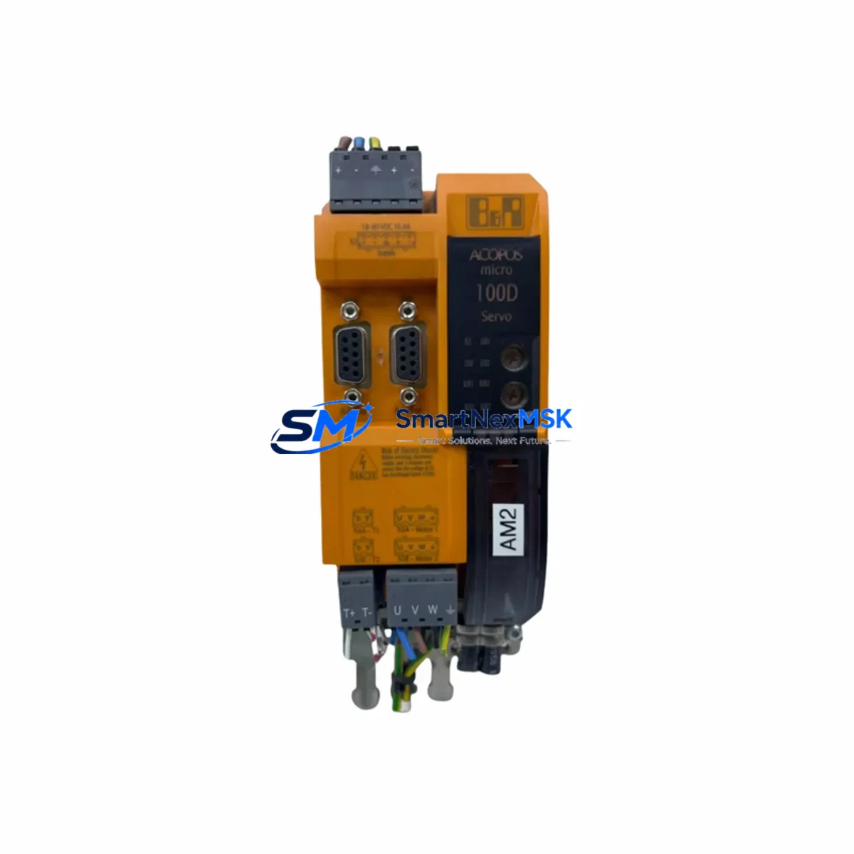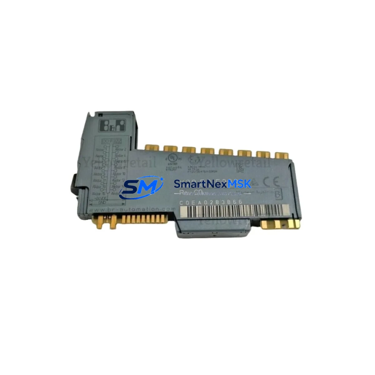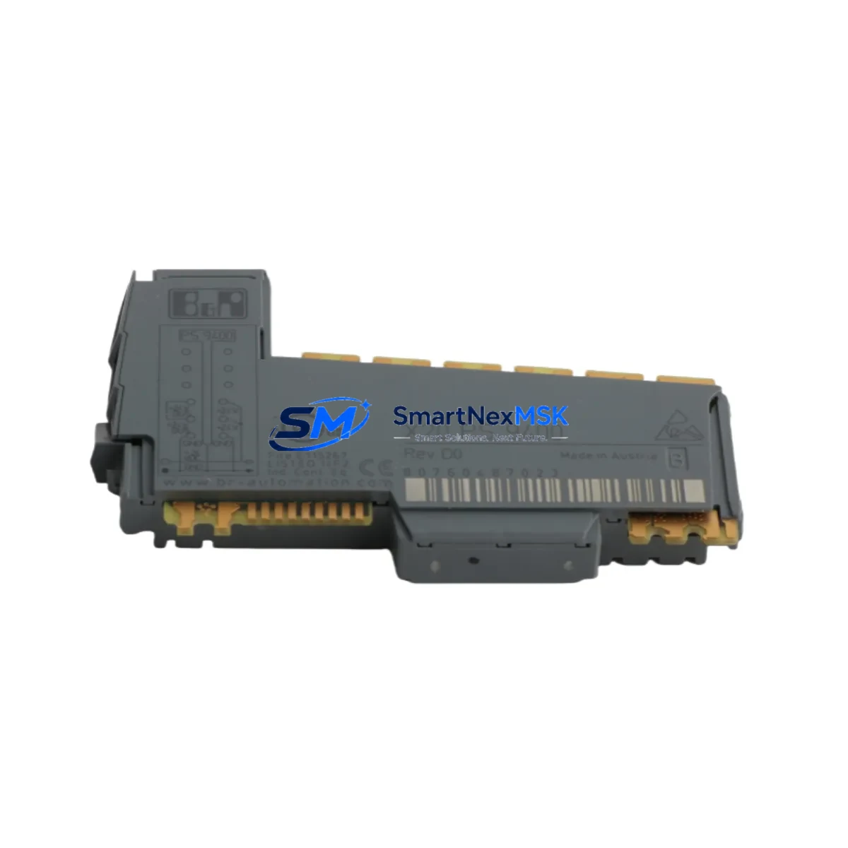
B&R X20PS9400 Maintenance-Ready Spare for X20 Automation
The B&R X20PS9400 is an internal power supply module designed for the X20 Series modular PLC platform. In industrial automation environments where uptime is non-negotiable, maintaining a verified spare of the X20PS9400 is a fundamental element of any proactive maintenance strategy. Whether you are managing a high-cycle packaging line, a continuous process control system, or a multi-axis motion application, an unexpected power supply failure can cascade into extended unplanned downtime. Sourcing a tested, original-specification X20PS9400 replacement in advance eliminates that risk entirely.
This module provides the internal bus power required to sustain the X20 backplane and connected I/O nodes. Its compact DIN-rail form factor integrates directly into the X20 CPU station without additional wiring complexity, making field replacement straightforward for maintenance engineers familiar with the X20 architecture. Each unit dispatched from our inventory undergoes functional verification prior to shipment, and is covered by a 12-month warranty against manufacturing defects and operational failure.
Spare Maintenance Table
| Parameter | Specification / Detail |
|---|---|
| Part Number / SKU | X20PS9400 |
| Brand | B&R Industrial Automation |
| Series | X20 Modular PLC System |
| Module Function | Internal Power Supply for X20 Bus Controller / CPU Station |
| Mounting | DIN Rail, X20 Backplane Slot |
| Origin | Austria |
| Compatibility | X20 Series CPU stations, X20BC (Bus Controllers), X20 I/O expansion nodes |
| Application Environment | Industrial control cabinets, IEC 61131-3 automation systems, process and discrete manufacturing |
| Installation | Direct backplane insertion; no additional power wiring required for internal bus supply |
| Pre-Shipment Testing | Functional verification performed on every unit |
| Warranty | 12 Months — covers manufacturing defects and operational failure |
| Condition | Original spare, new or fully refurbished to OEM specification |
| Lead Time | In stock — same-day or next-business-day dispatch available |
Maintenance Planning for Continuous Operation
When a maintenance or procurement engineer schedules a replacement of the X20PS9400, the power supply module rarely fails in isolation. A thorough site inspection and cabinet audit should accompany any planned or emergency replacement to prevent repeat failures and ensure the restored system operates reliably through the next maintenance interval.
Begin by inspecting the X20CP1484 or X20CP3485 CPU module seated in the same station. Power anomalies that stress the X20PS9400 often originate from CPU-side load spikes or firmware-level power management issues. Confirm the CPU firmware version is current and that no diagnostic flags are logged in Automation Studio prior to reinstating the power supply.
Next, audit the X20BM11 or X20BM05 bus modules connecting the I/O nodes downstream. Corroded or mechanically stressed bus connectors can introduce intermittent load conditions that accelerate power supply wear. Replace any bus module showing physical damage or elevated contact resistance.
The X20DO9322 digital output modules and X20AI4622 analog input modules in the same rack should be checked for correct load draw. Overloaded output channels or shorted field wiring can place sustained overcurrent demand on the internal bus supply, directly shortening the X20PS9400 service life. Use the I/O diagnostic pages in Automation Studio to verify channel-level current consumption.
For cabinets operating in environments with high ambient temperature or poor ventilation, inspect the X20IF1041 POWERLINK communication interface and any X20IF10D1 EtherNet/IP interface modules for thermal stress indicators. Communication modules generate additional bus load and heat; ensuring adequate cabinet cooling directly protects the power supply module.
Do not overlook the 24 VDC external power supply feeding the X20 station. A degraded SITOP, Phoenix Contact QUINT, or equivalent DIN-rail PSU delivering voltage outside the 24 V ±20% tolerance will cause the X20PS9400 to operate outside its design envelope. Measure supply voltage under full load before commissioning the replacement module.
Finally, inspect the terminal blocks and field wiring at the I/O modules. Loose terminals, corroded conductors, or undersized cable cross-sections create resistive heating that elevates cabinet temperature and indirectly stresses all power-handling components, including the X20PS9400. A complete terminal torque check is recommended as part of any planned maintenance event involving power supply replacement.
Site Replacement Workflow
Replacing the X20PS9400 in the field is a structured process that, when executed correctly, minimises system downtime to under 30 minutes for a prepared maintenance team.
Step 1 — Preparation: Download the current X20 project from Automation Studio and back up the CPU configuration. Confirm the replacement X20PS9400 part number matches the installed module exactly, including any hardware revision suffix if applicable to your system version.
Step 2 — Safe Isolation: Follow your site LOTO (Lockout/Tagout) procedure. De-energise the 24 VDC supply to the X20 station. Do not attempt hot-swap of the internal power supply module — the X20PS9400 is not rated for live insertion in standard configurations.
Step 3 — Module Removal: Release the X20 locking mechanism and slide the X20PS9400 out of the backplane slot. Inspect the backplane connector for pin damage or contamination before inserting the replacement.
Step 4 — Replacement Installation: Insert the new X20PS9400 firmly into the backplane slot until the locking tab engages. Restore 24 VDC power and observe the module status LED. A solid green indication confirms correct initialisation.
Step 5 — System Verification: Reconnect Automation Studio, perform a full I/O diagnostic scan, and verify all process values are within expected ranges before returning the system to production. Log the replacement in your CMMS with the module serial number and installation date to support future warranty claims and lifecycle tracking.
Maintaining one or two X20PS9400 units in your on-site spare parts inventory is strongly recommended for any facility running B&R X20-based control systems. Long-term supply continuity, combined with our 12-month warranty and pre-shipment testing commitment, makes this the lowest-risk sourcing strategy for critical automation spare parts.
Spare Parts Support FAQ
Q1: Is the X20PS9400 still available as a new original spare, or only as a refurbished unit?
We stock both new original and fully refurbished-to-OEM-specification units. All units, regardless of condition grade, are functionally tested before dispatch and carry the same 12-month warranty. The condition is confirmed at the time of order.
Q2: How do I verify compatibility between the X20PS9400 and my existing X20 CPU station?
Compatibility is determined by the X20 station type and hardware revision. The X20PS9400 is designed for use within standard X20 CPU stations. Provide your CPU module part number and hardware revision when placing your order, and our technical team will confirm compatibility before shipment.
Q3: What is included in the pre-shipment testing process?
Each X20PS9400 is powered up and subjected to a functional load test to verify internal bus voltage output, thermal stability, and status LED behaviour. Units that do not meet OEM performance thresholds are not dispatched. A test report is available on request for quality-critical applications.
Q4: What does the 12-month warranty cover, and how is a warranty claim processed?
The warranty covers failure due to manufacturing defects or operational malfunction under normal industrial operating conditions. It does not cover damage caused by incorrect installation, overvoltage events, or physical impact. To initiate a claim, contact our support team with the order reference and a description of the failure mode. We will arrange return logistics and provide a replacement or repair within an agreed lead time.
© 2026 SMARTNEXMSK. All rights reserved.
Original Source: https://smartnexmsk.com
Contact: [email protected] | +86 18259474341