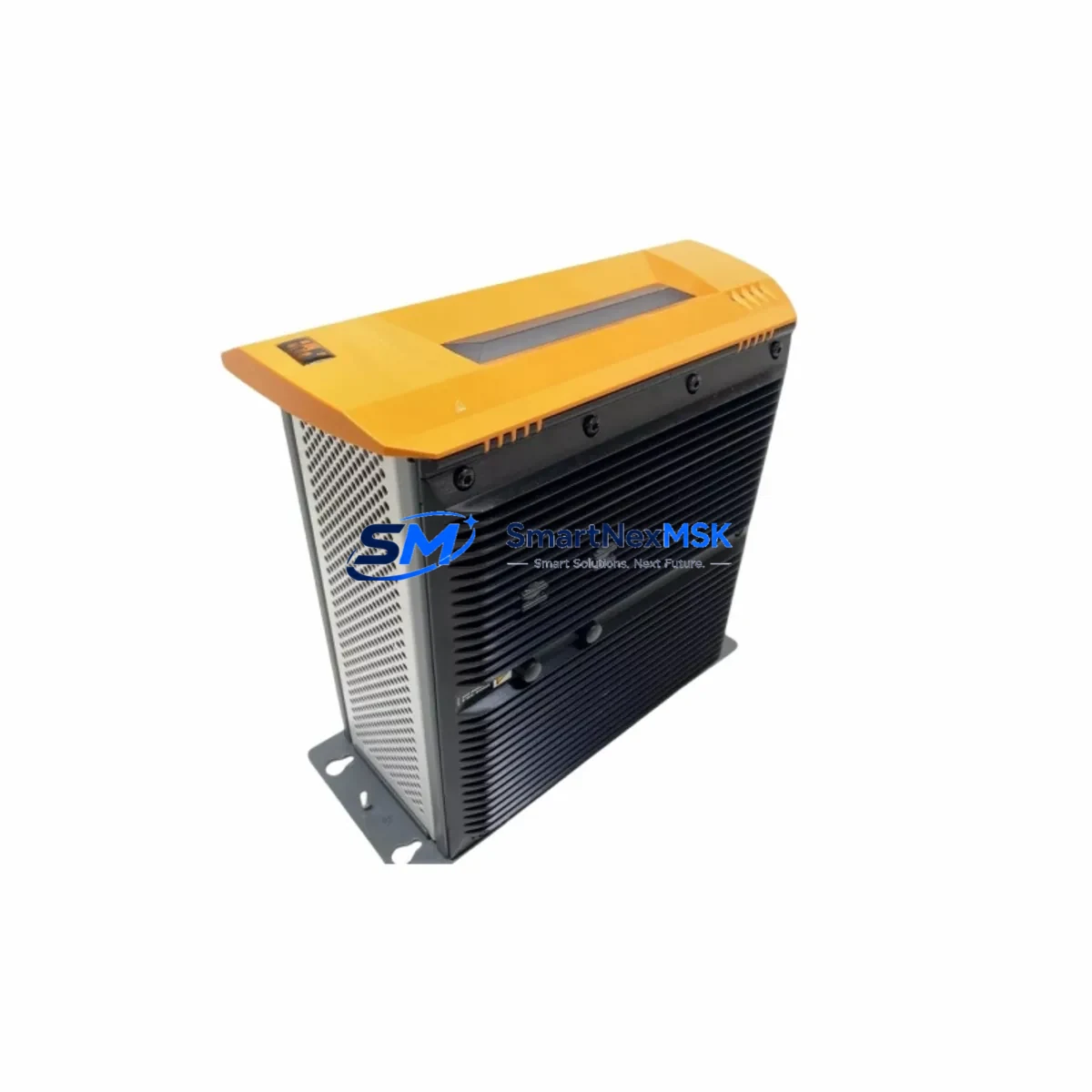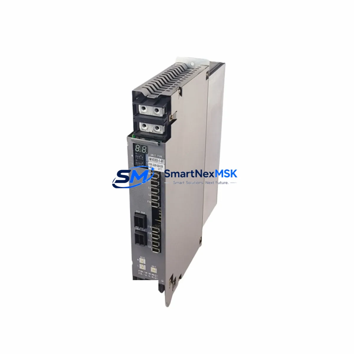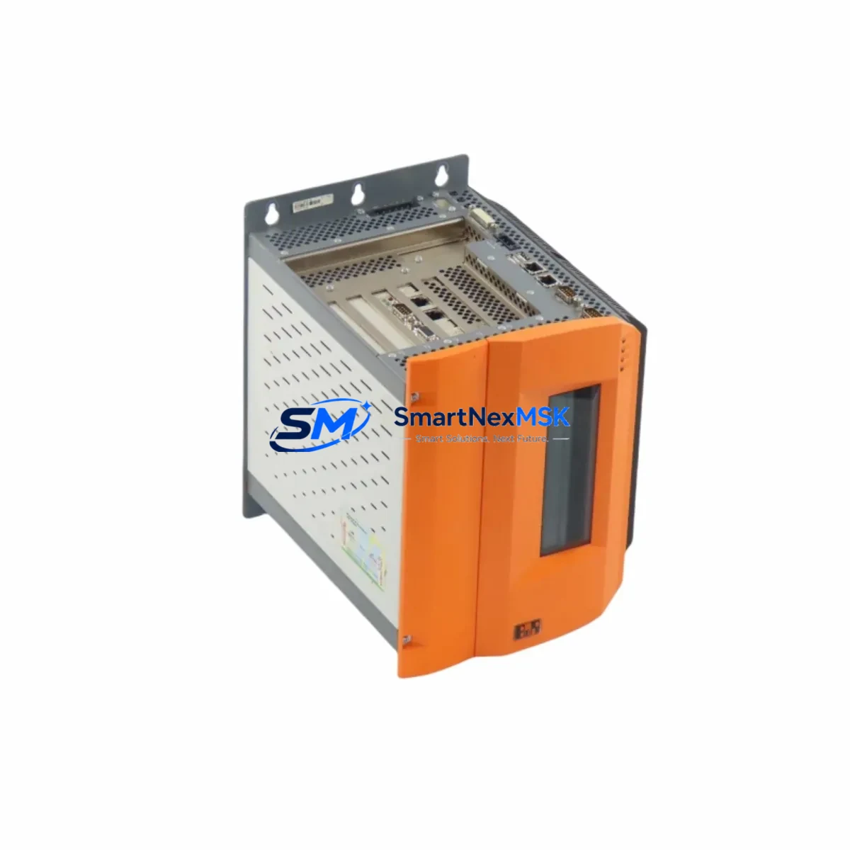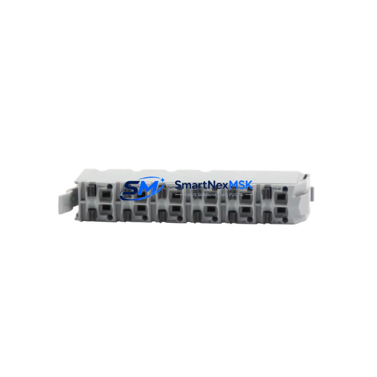
B&R X20TB12 Retrofit-Ready Terminal Block for X20 Control Systems
The B&R X20TB12 is a 12-pin plug-in terminal block designed for seamless integration with the B&R X20 I/O module family. As a drop-in replacement component, the X20TB12 is widely used in legacy system retrofits, control cabinet upgrades, and I/O expansion projects across discrete manufacturing, process automation, and machine building applications. Whether you are replacing a worn connector on an aging production line or commissioning a new X20 node in a modernized control architecture, the X20TB12 delivers the wiring compatibility and mechanical reliability that industrial environments demand.
In retrofit scenarios, the X20TB12 is typically paired with I/O modules such as the X20DI9371 (12-channel digital input) or the X20DO9322 (12-channel digital output), both of which share the same 12-pin terminal footprint. Engineers migrating from older B&R 2003 or 2005 system platforms to the X20 architecture frequently encounter wiring harnesses that were originally terminated on legacy connectors. The X20TB12 allows field wiring to be re-terminated without rerouting cable runs, significantly reducing retrofit labor hours and minimizing the risk of wiring errors during cutover.
When planning a retrofit involving the X20TB12, engineers should verify several key parameters before committing to the replacement. First, confirm that the field wiring conductor cross-section is within the X20TB12’s accepted range (0.5 mm² to 1.5 mm², solid or stranded). Second, check that the terminal block insertion direction matches the module orientation on the X20 backplane bus or X20BM11 bus module carrier. Third, validate that the I/O module address assignment in the B&R Automation Studio project matches the physical slot position after any rack reconfiguration. Incorrect slot addressing is one of the most common causes of I/O communication faults following a module swap.
For systems using the X20BC0083 POWERLINK bus controller or the X20BC0073 Ethernet POWERLINK interface, the X20TB12 terminal replacement does not affect the communication layer — POWERLINK cycle time, node address, and station number settings remain intact in the controller configuration. However, if the retrofit involves replacing an entire I/O station rather than just the terminal block, engineers must re-download the hardware configuration from Automation Studio and perform a cold restart of the X20CP1586 or equivalent X20 CPU module to re-enumerate the I/O map.
In control cabinets where the X20TB12 is used alongside X20PS9400 internal power supply modules and X20IF1061 interface modules, it is important to de-energize the segment before removing or inserting terminal blocks. Although the X20 system supports hot-swapping of I/O modules under certain firmware conditions, terminal block removal while the segment is live can cause transient voltage spikes that may affect neighboring modules on the same bus segment. Always follow the de-energization procedure documented in the B&R X20 System User’s Manual (revision 3.10 or later).
For HMI integration, if the retrofitted I/O point is mapped to a visualization object in a B&R Power Panel or a third-party SCADA system via OPC UA, verify that the process variable tag address has not shifted after the module replacement. Tag address drift is a common issue when modules are removed and re-inserted in a different slot order, particularly in systems where I/O addressing is slot-based rather than node-based. Update the HMI screen bindings and perform a full I/O force test before returning the line to production.
SMARTNEXMSK maintains verified stock of the X20TB12 and related X20 series components. All units are sourced from authorized distribution channels, inspected prior to shipment, and covered by a 12-month warranty against manufacturing defects. Expedited shipping is available for urgent MRO and line-down situations.
Upgrade Compatibility Table
| Parameter | X20TB12 Specification | Retrofit Notes |
|---|---|---|
| Pin Count | 12-pin plug-in terminal | Compatible with all 12-pin X20 I/O modules |
| Conductor Cross-Section | 0.5 – 1.5 mm² (solid/stranded) | Verify existing field wiring gauge before re-termination |
| Installation Method | Plug-in, tool-free removal | De-energize segment before removal; no special tools required |
| Communication Compatibility | Passive terminal — protocol-agnostic | No impact on POWERLINK, Modbus, or PROFIBUS configuration |
| Compatible Modules | X20DI9371, X20DO9322, X20AI4622, X20AO4622 | Confirm module pin count matches before ordering |
| Backplane / Carrier | X20BM11 bus module | Check carrier slot alignment after installation |
| Commissioning Check | I/O force test recommended post-installation | Verify tag addresses in Automation Studio and HMI |
| Warranty | 12-Month Warranty | Covers manufacturing defects; includes pre-shipment inspection |
Retrofit Planning for Existing Automation Systems
A successful X20TB12 retrofit begins with a thorough audit of the existing control cabinet. Start by documenting the current wiring schedule for each terminal position — this is especially critical in systems where field cables were labeled by terminal number rather than signal name. In older installations using the B&R 2003 system or early X20 revisions, terminal labeling conventions may differ from current Automation Studio documentation, requiring cross-reference with the original electrical drawings.
Once the wiring audit is complete, prepare the replacement terminal block and verify that the locking tab mechanism is undamaged. In high-vibration environments such as press lines or conveyor systems, terminal blocks can develop micro-fractures in the locking tab over time, leading to intermittent contact faults. The X20TB12’s robust thermoplastic housing is rated for the mechanical stress typical of these environments, but visual inspection before installation is always recommended.
For systems that include X20AI4622 analog input modules or X20AO4622 analog output modules, pay particular attention to shielding continuity when re-terminating signal wires. Analog signal integrity is highly sensitive to ground loop interruptions, and any break in shield continuity during the terminal swap can introduce noise that affects process control accuracy. Use a continuity tester to verify shield connections before and after the swap.
In multi-rack configurations using the X20IF10D1 X2X Link interface module to extend the I/O bus across cabinet sections, confirm that the X2X Link cable is not disturbed during the terminal replacement. X2X Link is a synchronous bus, and any interruption — even momentary — will cause the entire downstream I/O segment to go offline until the link is re-established and the CPU completes its re-initialization cycle. Plan the terminal swap during a scheduled maintenance window to avoid unplanned production stops.
Programming cable access via the X20 USB programming interface or Ethernet port on the CPU module should be maintained throughout the retrofit to allow real-time monitoring of I/O status in Automation Studio’s I/O Mapping view. This enables the commissioning engineer to confirm signal state immediately after re-termination without requiring a full system restart.
Downtime Control During System Migration
Minimizing downtime during an X20TB12 replacement requires preparation, sequencing, and a clear rollback plan. Before beginning, export the current Automation Studio project and save a backup of the CPU’s runtime configuration. This ensures that if an unexpected fault occurs during the swap — such as a wiring error that triggers an I/O module protection response — the system can be restored to its pre-retrofit state without re-engineering effort.
Where production schedules permit, perform the terminal block swap during a planned shift changeover or scheduled preventive maintenance window. If the retrofit must be performed during production, isolate the affected I/O segment using the X20 system’s segment power switch on the X20PS9400 power supply module, rather than shutting down the entire control system. This approach keeps the CPU and communication backbone active, preserving SCADA connectivity and historian data continuity while the physical swap is performed.
After re-termination, perform a structured commissioning sequence: first verify continuity on all 12 terminals, then restore segment power and observe the module status LED on the associated I/O module. A solid green LED confirms successful module recognition and I/O map synchronization. If the LED flashes red, check the terminal seating and re-inspect the wiring against the original schedule. Do not return the line to automatic mode until all I/O points have been individually force-tested and confirmed in Automation Studio.
For systems with safety I/O integrated into the same cabinet — such as those using X20SI9100 safety input modules — ensure that the safety function validation procedure is repeated after any wiring work in the cabinet, in accordance with IEC 62061 or ISO 13849 requirements. Safety function re-validation is a mandatory step that cannot be bypassed, regardless of whether the safety wiring itself was touched during the retrofit.
Retrofit Support FAQ
Q1: Is the X20TB12 a direct drop-in replacement for the terminal block on my existing X20 I/O module?
Yes. The X20TB12 is the standard 12-pin plug-in terminal block for the B&R X20 I/O module family. It is mechanically and electrically compatible with all X20 modules that use a 12-pin terminal interface, including digital input, digital output, and analog I/O variants. No adapter or modification is required.
Q2: Do I need to re-download my Automation Studio program after replacing the X20TB12?
No. The X20TB12 is a passive wiring component and does not contain any firmware or configuration data. Replacing the terminal block does not alter the I/O module’s identity or its address on the X20 bus. A program re-download is only required if the I/O module itself is replaced or if the module’s slot position in the rack changes.
Q3: What wiring checks should I perform before and after the terminal block swap?
Before the swap, document the wire position for each of the 12 terminals using the existing wiring schedule or electrical drawings. After re-termination, use a continuity tester to verify each connection, check for correct polarity on power and signal terminals, and confirm shield continuity on analog channels. Restore segment power and perform an I/O force test in Automation Studio to validate all signal states before returning to automatic operation.
Q4: What does the 12-month warranty cover, and how is it handled?
All X20TB12 units supplied by SMARTNEXMSK are covered by a 12-month warranty against manufacturing defects, including terminal contact failure, housing cracking, and locking tab breakage under normal operating conditions. Each unit undergoes pre-shipment inspection before dispatch. In the event of a warranty claim, contact our technical team at [email protected] with the order reference and a description of the fault. Replacement units are dispatched within 2 business days of claim verification.
© 2026 SMARTNEXMSK. All rights reserved.
Original Source: https://smartnexmsk.com
Contact: [email protected] | +86 18259474341