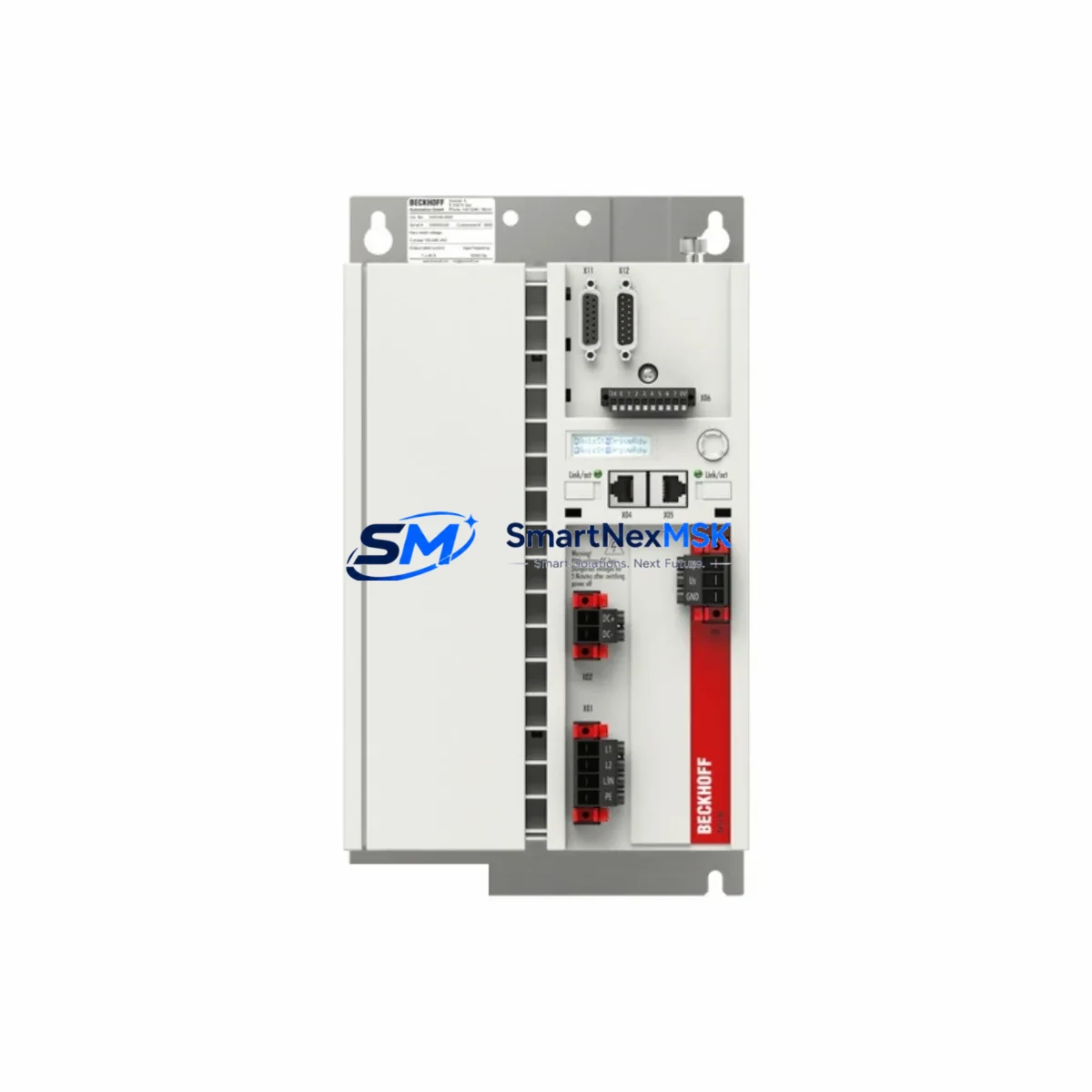
BECKHOFF AX5118-0000-0200: Retrofit-Ready Servo Drive for AX5000 Series Control Systems
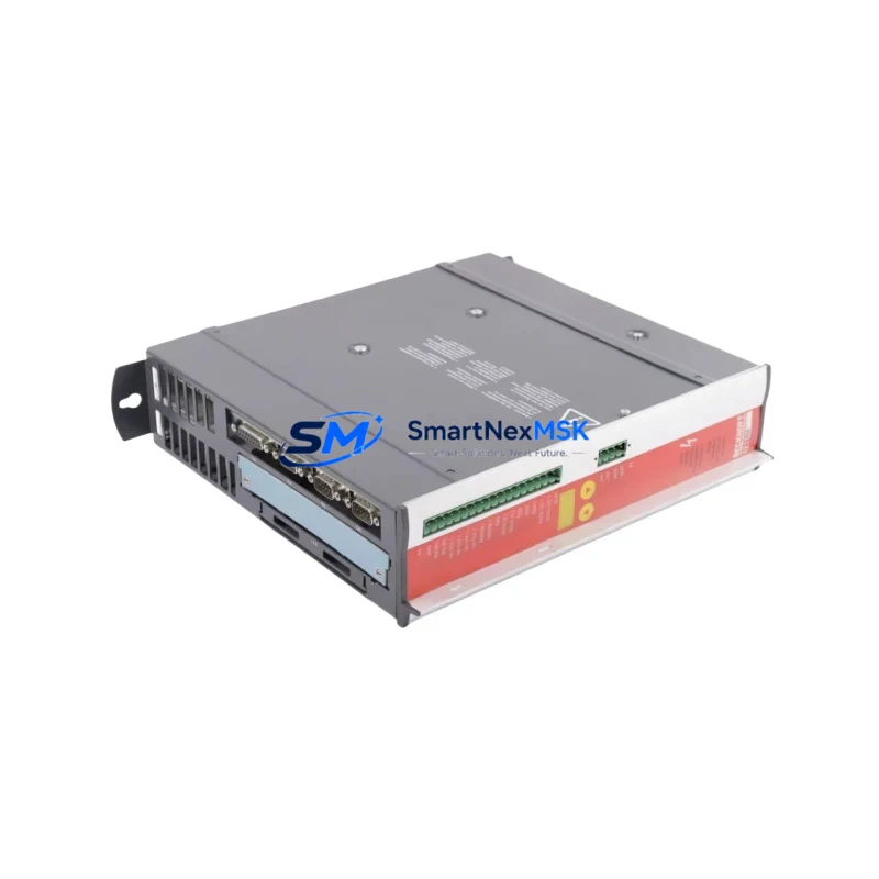
The BECKHOFF AX5118-0000-0200 is a single-axis digital compact servo drive from the AX5000 Series, rated at 18A continuous output current and designed for seamless integration into TwinCAT-based motion control architectures. As legacy AX5000 installations age and original units reach end-of-service, the AX5118-0000-0200 serves as the authoritative retrofit and replacement solution — preserving existing wiring infrastructure, EtherCAT topology, and NC axis configurations without requiring a full control system redesign.
Whether you are recovering from an unplanned drive failure, executing a planned control cabinet upgrade, or migrating from an earlier AX5000 variant such as the AX5106-0000-0200 or AX5112-0000-0200, this unit delivers the electrical and firmware compatibility required to restore production continuity with minimal downtime. The drive interfaces directly with the AX5000 power supply module (e.g., AX5901 or AX5902 DC link capacitor module) and mounts on standard DIN rail or panel within the existing cabinet footprint.
Upgrade Compatibility Table
| Parameter | AX5118-0000-0200 (This Unit) | Retrofit Notes |
|---|---|---|
| Series | AX5000 Single-Axis | Compatible with all AX5000 rack and cabinet layouts |
| Continuous Output Current | 18A | Verify motor nameplate; replaces AX5112 (12A) only with motor re-sizing |
| Supply Voltage | 3 × 400–480 VAC, 50/60 Hz | Confirm panel supply matches; no transformer required in standard EU/CN installations |
| Communication Interface | EtherCAT (CoE, DS402) | Direct drop-in on existing EtherCAT ring; no topology change needed |
| Feedback Systems | EnDat 2.2, Hiperface, Resolver, SinCos | Confirm encoder type on motor; cable pinout identical to prior AX5000 units |
| Mounting | Panel / DIN rail, 75mm width | Same footprint as AX5106/AX5112/AX5118 predecessors |
| TwinCAT Compatibility | TwinCAT 2 & TwinCAT 3 | No NC axis re-parameterization required if replacing same current class |
| Brake Output | 24 VDC, integrated | Existing brake wiring reusable; verify 24V supply capacity |
| Warranty | 12 Months | Covered from date of shipment; includes functional test certificate |
| Replacement Path | AX5106 → AX5112 → AX5118 | Upward current-class migration; review DC bus loading on AX5901/AX5902 |
Retrofit Planning for Existing Automation Systems
A successful AX5118-0000-0200 retrofit begins well before the unit arrives on-site. Engineers should pull the existing TwinCAT project and document the NC axis parameters — including axis ID, encoder resolution, velocity limits, and following-error windows — so these can be verified against the replacement drive after installation. The AX5000 Series uses a standardized EtherCAT slave information (ESI) file, meaning the AX5118-0000-0200 will be recognized automatically by TwinCAT System Manager without manual ESI import in most installations.
On the hardware side, the retrofit checklist should cover the following areas. First, confirm the AX5901 DC link capacitor module or AX5902 regenerative supply is rated for the combined axis current draw after the new 18A unit is added. Second, inspect the ZK4500 motor power cable and ZK4510 feedback cable — both are reusable if undamaged, and their connectors are mechanically identical across the AX5000 current classes. Third, verify the 24 VDC auxiliary supply feeding the drive’s logic and brake circuit; the AX5118 draws approximately 0.5A on the 24V rail, consistent with other AX5000 units.
For cabinet-level integration, the AX5000 power supply module terminal block layout and the EtherCAT IN/OUT RJ45 ports are in identical positions across all AX5000 single-axis variants, so no rewiring of the EtherCAT daisy chain is required. If the installation includes an AX5801 option card (e.g., for multi-encoder or safety functions), confirm the card is seated correctly after drive swap — option cards are hot-swappable in some firmware versions but should be re-seated with power off during a retrofit.
HMI screens built on CP6606 or CP2916 Panel PCs running TwinCAT HMI (TE2000) typically reference axis names rather than hardware addresses, so existing operator screens will function without modification after the drive replacement. However, if the previous drive had a custom axis name or ADS port assignment, verify these match in the TwinCAT project before going live. Communication links to upstream CX2040 or CX5140 Embedded PCs via EtherCAT remain unaffected as long as the slave address (fixed or auto-increment) is preserved.
I/O expansion modules such as the EL2004 digital output terminal or EL3062 analog input terminal connected on the same EtherCAT segment are not impacted by the drive swap. Their process data mappings in the TwinCAT PLC project remain valid. If the retrofit also involves upgrading adjacent EL7201 or EL7211 servo terminals on the same bus coupler, coordinate the firmware update sequence to avoid EtherCAT state machine conflicts during commissioning.
Downtime Control During System Migration
Minimizing production downtime during an AX5118-0000-0200 swap requires a structured pre-commissioning approach. Before powering down the cabinet, use TwinCAT Scope View to capture a baseline motion profile — velocity, torque, and position traces — from the existing drive. This reference data allows engineers to validate that the replacement unit is performing identically before handing the line back to production.
The recommended sequence is: (1) export the full TwinCAT project backup including NC configuration and PLC program; (2) power down the cabinet and lock out the supply; (3) disconnect the ZK4500 motor cable and ZK4510 feedback cable, labeling each connector; (4) remove the failed AX5118 unit and install the replacement, re-seating any AX5801 option cards; (5) reconnect all cables and restore 24V auxiliary power first to verify EtherCAT link before applying mains; (6) bring TwinCAT online, confirm the drive appears in the EtherCAT topology scan, and activate the NC configuration; (7) run a slow-speed jog cycle to verify encoder direction, brake release, and following-error behavior before resuming automatic mode.
Each unit shipped by SMARTNEXMSK undergoes a functional output test prior to dispatch, with a test certificate included in the packaging. This eliminates the risk of commissioning a DOA unit and further compresses on-site downtime. With pre-staged hardware and a prepared TwinCAT backup, most AX5118-0000-0200 replacements are completed within a single shift.
Retrofit Support FAQ
Q1: Is the AX5118-0000-0200 a direct drop-in replacement for the AX5118-0000-0100?
A: Yes. The -0200 hardware revision is backward-compatible with the -0100 variant in terms of mounting dimensions, connector positions, and EtherCAT interface. Firmware is updated automatically by TwinCAT upon first connection. No NC axis re-parameterization is required when replacing the same current class.
Q2: What wiring changes are needed when retrofitting from an AX5112 to an AX5118?
A: The motor power connector (ZK4500 series) and feedback connector (ZK4510 series) are mechanically identical. No rewiring is required. However, verify that the motor’s continuous current rating is compatible with the 18A output of the AX5118 and that the DC bus supply (AX5901/AX5902) can support the increased current headroom.
Q3: How do I verify EtherCAT communication after installation?
A: Open TwinCAT System Manager, perform a network scan, and confirm the AX5118-0000-0200 appears as an EtherCAT slave with state OP (Operational). Check that the ESI device description matches and that the NC axis is linked to the correct drive instance. Run a manual jog at reduced speed to confirm encoder feedback and torque response before enabling automatic sequences.
Q4: What does the 12-month warranty cover?
A: The 12-month warranty covers manufacturing defects and functional failures under normal operating conditions from the date of shipment. Each unit is pre-tested before dispatch and ships with a functional test certificate. Warranty claims are processed via [email protected] with a fault description and order reference. Physical damage caused by incorrect installation or overvoltage is excluded.
© 2026 SMARTNEXMSK. All rights reserved.
Original Source: https://smartnexmsk.com
Contact: [email protected] | +86 18259474341