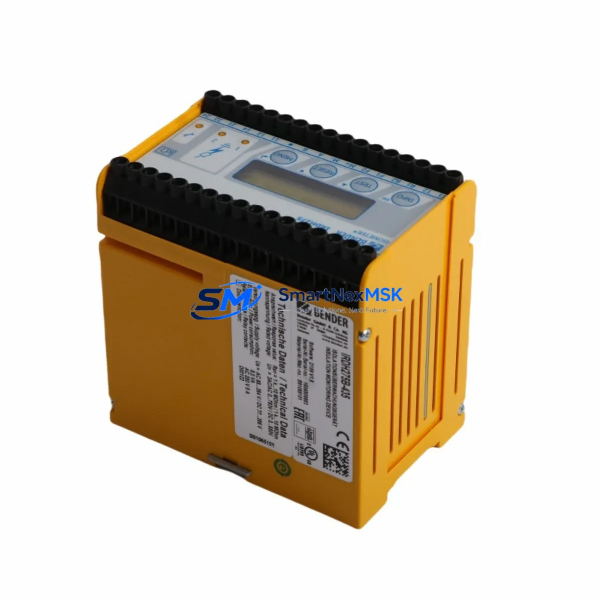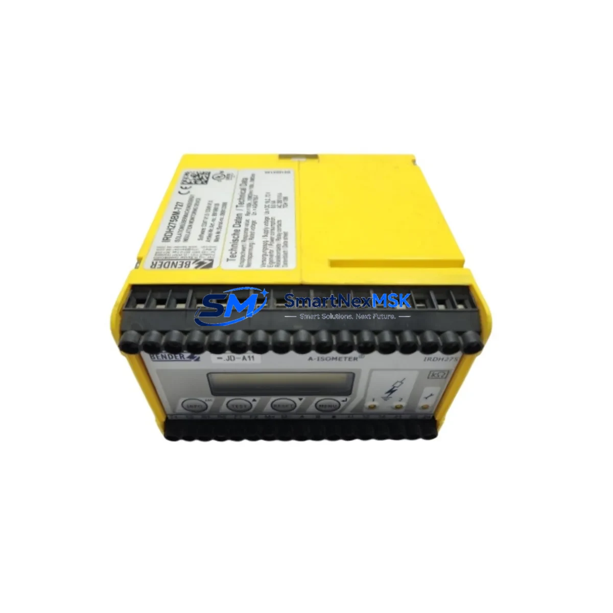
BENDER IRDH275B-435: Retrofit-Ready Insulation Monitoring for IRDH275 Control Systems
The BENDER IRDH275B-435 is a high-performance insulation monitoring device engineered for ungrounded IT power systems (IT systems) in industrial, medical, and critical infrastructure environments. As a direct retrofit replacement for the legacy IRDH275 series, the IRDH275B-435 delivers seamless compatibility with existing panel layouts, terminal wiring, and system architectures — minimizing downtime and eliminating the need for costly control cabinet redesigns during modernization projects.
Whether you are upgrading an aging power distribution panel, replacing a discontinued insulation monitor in a hospital operating theatre, a marine vessel, or an industrial process line, the IRDH275B-435 is engineered to slot into your existing infrastructure with minimal intervention. Its wide measuring voltage range, integrated alarm relay outputs, and RS-485 / Modbus RTU communication interface make it a future-proof choice for both standalone monitoring and networked building management or SCADA integration.
Upgrade Compatibility Table
| Parameter | IRDH275 (Legacy) | IRDH275B-435 (Retrofit) |
|---|---|---|
| Nominal System Voltage | AC/DC up to 690 V | AC/DC up to 690 V |
| Measuring Frequency | 0 Hz / 50 Hz / 60 Hz | 0 Hz / 50 Hz / 60 Hz |
| Communication Interface | Analog output / relay | RS-485 / Modbus RTU (built-in) |
| Alarm Relay Outputs | 2 relay outputs | 2 relay outputs (compatible wiring) |
| Mounting / Form Factor | DIN rail / panel mount | DIN rail / panel mount (same footprint) |
| Terminal Compatibility | Screw terminals | Screw terminals (direct re-use) |
| Coupling Device Compatibility | AGH / EDS series | AGH / EDS series (fully compatible) |
| Retrofit Recommendation | — | Direct drop-in; verify address setting |
| Commissioning Focus | Manual calibration | Auto-calibration + Modbus address config |
| Warranty | Discontinued / no support | 12-Month Warranty (SMARTNEXMSK) |
Retrofit Planning for Existing Automation Systems
Replacing an IRDH275 with the IRDH275B-435 in an operational control cabinet requires a structured approach to ensure continuity of insulation monitoring and alarm logic. Before beginning the swap, engineers should document the existing terminal wiring layout — particularly the connections to the BENDER AGH420 coupling device or AGH150W if used in conjunction with a locating system. The coupling device remains in place and is fully compatible with the IRDH275B-435, eliminating the need to disturb the primary IT system wiring.
Power supply to the monitoring device is typically drawn from the monitored IT system itself or from an auxiliary 24 V DC supply rail. Confirm the supply voltage matches the IRDH275B-435 specification (AC 0–460 V or DC 0–460 V) before energizing. If the existing cabinet uses a BENDER ISOMETER iso685 or iso1685P in a parallel monitoring zone, ensure that only one active insulation monitor is connected per IT system segment to avoid measurement interference.
For systems that previously relied on the IRDH275‘s analog output for integration with a BENDER BMS (Building Management System) or a third-party SCADA platform, the IRDH275B-435’s native Modbus RTU over RS-485 interface provides a significant upgrade path. Configure the device address (default: 1) and baud rate via the front panel DIP switches before installation. If the existing network already includes other BENDER devices such as the RCMS460 residual current monitoring system or the EDS460 insulation fault locating system, assign a unique Modbus node address to avoid bus conflicts.
Terminal block re-use is straightforward: the IRDH275B-435 maintains the same terminal designations for the system connection (L1/L2 or +/-), PE reference, and alarm relay outputs (K1/K2). If the legacy installation used a BENDER MK2430 or similar measuring current transformer for high-impedance system monitoring, verify the transformer’s secondary output is within the IRDH275B-435’s input range. For cabinets housing a BENDER CP700 control panel or PGH471 alarm annunciator, the relay output wiring from the IRDH275B-435 connects directly to the existing alarm input terminals without modification.
Where the retrofit is part of a broader I/O expansion — for example, adding a BENDER EDS460-D fault locating system to an existing monitoring loop — plan the bus topology in advance. The EDS460-D and IRDH275B-435 share the same RS-485 bus and are designed to operate as a coordinated system, with the IRDH275B-435 triggering the EDS460-D’s locating cycle upon alarm. This integration eliminates the need for manual fault tracing and significantly reduces the time required to identify and isolate a first fault in complex IT network installations.
Downtime Control During System Migration
Minimizing production interruption during an insulation monitor replacement is a primary concern in critical IT system environments — particularly in hospitals, data centers, and continuous process industries where an unplanned shutdown carries significant operational and safety consequences.
The recommended approach is to pre-configure the IRDH275B-435 on the bench before installation. Set the response value (Ran), alarm thresholds, Modbus address, and baud rate in advance using the front panel interface. This reduces in-cabinet commissioning time to under 15 minutes for a straightforward swap. Where the system permits a brief de-energization window, the terminal-for-terminal replacement can be completed without rewiring — simply transfer the existing conductors from the IRDH275’s terminals to the corresponding terminals on the IRDH275B-435.
For systems where continuous monitoring is mandatory (e.g., medical IT systems per IEC 60364-7-710), coordinate the replacement with the facility’s electrical safety officer and schedule the swap during a planned maintenance window. Use a temporary portable insulation monitor to maintain monitoring continuity during the changeover if required by local regulations or site safety procedures.
After installation, perform a functional test by verifying that the IRDH275B-435 displays the correct system insulation resistance value and that both alarm relays respond correctly to a simulated fault condition using a test resistor. Confirm Modbus communication by polling the device from the SCADA or BMS host. Log the commissioning results and retain them as part of the system’s maintenance record. All units supplied by SMARTNEXMSK are pre-tested prior to dispatch, with a 12-month warranty covering device defects under normal operating conditions.
Retrofit Support FAQ
Q1: Is the IRDH275B-435 a direct drop-in replacement for the IRDH275?
Yes. The IRDH275B-435 is designed as a functional and dimensional replacement for the IRDH275. Terminal designations, mounting dimensions, and coupling device compatibility are maintained. The primary addition is the integrated RS-485 / Modbus RTU interface, which requires a Modbus address to be configured if network integration is used. If the legacy installation used only relay outputs, no additional configuration is required beyond setting the alarm thresholds.
Q2: What wiring changes are required during the retrofit?
In most installations, no rewiring is necessary. The IRDH275B-435 uses the same terminal layout as the IRDH275 for system connection, PE reference, and alarm relay outputs. If the existing installation includes an RS-485 bus for other BENDER devices, connect the A/B bus conductors to the IRDH275B-435’s RS-485 terminals and assign a unique node address. Always verify terminal tightening torque per the device datasheet after transfer.
Q3: How is compatibility with existing BENDER coupling devices and fault locators verified?
The IRDH275B-435 is compatible with the full range of BENDER AGH and EDS series coupling devices and fault locating systems. Verify compatibility by confirming that the coupling device’s output current range matches the IRDH275B-435’s measuring input specification. For EDS460 or EDS461 fault locating systems, the IRDH275B-435 acts as the master monitor and triggers the locating cycle via Modbus command or relay signal — no hardware modification to the EDS unit is required.
Q4: What does the 12-month warranty cover, and how are units tested before shipment?
All IRDH275B-435 units supplied by SMARTNEXMSK undergo functional testing prior to dispatch, including insulation resistance measurement verification, alarm relay output confirmation, and (where applicable) Modbus communication validation. The 12-month warranty covers manufacturing defects and device malfunction under normal operating conditions. It does not cover damage resulting from incorrect installation, overvoltage events, or unauthorized modification. Warranty claims are processed directly through SMARTNEXMSK — contact [email protected] for support.
© 2026 SMARTNEXMSK. All rights reserved.
Original Source: https://smartnexmsk.com
Contact: [email protected] | +86 18259474341