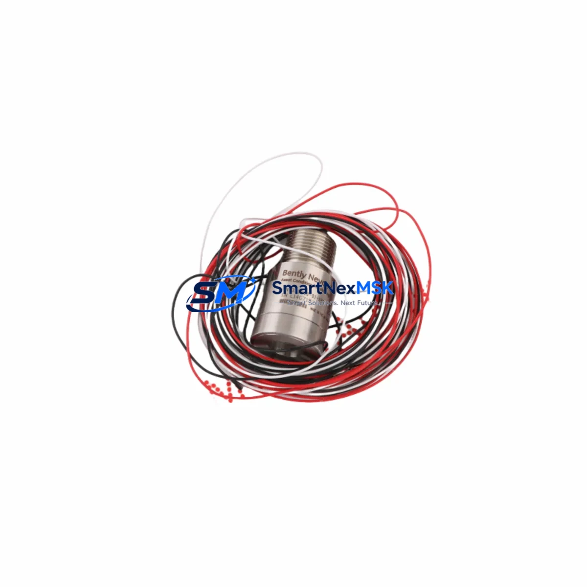
Bently Nevada 137074-01 Retrofit-Ready Proximitor for 3500 Series: Compatible Modernization and Smooth System Upgrade
The Bently Nevada 137074-01 is a Proximitor/Seismic Interface Module engineered for the 3500 Series machinery protection platform. As legacy vibration monitoring infrastructure ages across refineries, power generation facilities, and rotating equipment installations, the 137074-01 has become one of the most sought-after retrofit components for engineers tasked with maintaining continuous protection without full system replacement. Whether you are replacing a failed unit, upgrading a degraded signal chain, or migrating from an older 3300 Series rack to the 3500 architecture, this module delivers the compatibility and reliability your application demands.
The 137074-01 interfaces directly with eddy-current proximity probes and seismic velocity transducers, converting raw sensor signals into conditioned outputs readable by the 3500/22M Transient Data Interface or the 3500/42M Proximitor/Seismic Monitor. When planning a retrofit, engineers must verify that the existing probe cable lengths and extension cable assemblies — typically 5-metre or 9-metre configurations — remain within the gap voltage specification range of -10 VDC to -18 VDC. Confirming this before installation eliminates the most common source of post-retrofit calibration errors.
Upgrade Compatibility Table
| Parameter | Details |
|---|---|
| SKU / Part Number | 137074-01 |
| Compatible Platform | Bently Nevada 3500 Series Machinery Protection System |
| Module Function | Proximitor / Seismic Interface |
| Replaces / Upgrades From | 3300 Series Proximitor modules; earlier 3500 interface revisions |
| Backplane Interface | 3500 Series rack backplane — standard slot assignment |
| Communication Compatibility | Compatible with 3500/92 Communication Gateway (Modbus, Ethernet) |
| Installation Requirement | Rack power must be isolated before module insertion; verify slot addressing via System 1 software |
| Wiring Adaptation | Terminal block pinout matches 3500 Series standard; no rewiring required for direct replacement |
| Commissioning Note | Re-enter gap voltage, scale factor, and full-scale range in 3500 Rack Configuration Software after installation |
| Warranty | 12 Months — covers manufacturing defects and functional failure under normal operating conditions |
Retrofit Planning for Existing Automation Systems
A successful retrofit begins well before the module arrives on site. Start by auditing the existing 3500 rack assembly: confirm the chassis model, the number of occupied slots, and the firmware revision of the 3500/20 Rack Interface Module. If the rack is running firmware below revision 3.x, a firmware update may be required before the 137074-01 will be recognized correctly by System 1 condition monitoring software.
Power budget verification is equally critical. The 3500 Series rack draws power from a dedicated 3500/15 Power Supply Module, and adding or replacing interface modules changes the total current draw on the backplane. Confirm that the installed power supply has sufficient headroom — typically 5 A at 24 VDC — before proceeding. If the rack is near capacity, a second 3500/15 Power Supply Module may need to be added in a redundant configuration.
Terminal wiring for the 137074-01 follows the standard 3500 Series I/O terminal block layout. In most direct-replacement scenarios, the existing field wiring from the proximity probe and extension cable can be reconnected without modification. However, if the previous module was a 3300 Series unit, the terminal block pinout differs and a wiring adapter or re-termination will be required. Document all terminal assignments before disconnecting any wiring, and photograph the existing installation as a reference during recommissioning.
For sites running the 3500/92 Communication Gateway, verify that the Modbus register map or Ethernet/IP tag database reflects the correct slot address for the replaced module. Incorrect slot addressing is a frequent cause of HMI display errors after a module swap — the DCS or SCADA system may continue to read stale data from the old register address until the gateway configuration is updated. Coordinate with the control room team to update the 3500/92 configuration file and confirm that all vibration, gap, and alarm status tags are reading correctly before returning the machine to service.
Sites operating with a 3500/42M Proximitor/Seismic Monitor in the same rack should also verify that the channel configuration — including full-scale range, transducer scale factor, and alarm setpoints — is correctly transferred to the replacement 137074-01. Use the 3500 Rack Configuration Software to export the existing channel configuration before removal and import it after installation to minimize manual re-entry errors. If the site also uses a 3500/25 Enhanced Keyphasor Module for phase reference, confirm that the Keyphasor signal routing is unaffected by the module replacement.
Downtime Control During System Migration
Minimizing unplanned downtime during a module replacement requires a structured pre-outage checklist. Before isolating the rack, export a full configuration backup from the 3500 Rack Configuration Software and store it on a local engineering workstation — not solely on a network drive. This backup preserves all channel configurations, alarm setpoints, and communication parameters and allows rapid restoration if the replacement module requires re-configuration from scratch.
Where the process permits, schedule the module swap during a planned maintenance window aligned with the machine’s next scheduled outage. If an emergency replacement is required, coordinate with the operations team to place the affected channel in bypass mode within the 3500/20 Rack Interface Module before removing the 137074-01. This prevents spurious trips from propagating to the DCS or safety system during the swap interval.
After installation, perform a bench-level functional check before re-energizing the full rack: verify gap voltage output, confirm the OK relay status, and check that the module LED indicators match the expected state. Once the rack is re-energized, use System 1 software to confirm live vibration readings against a known reference — a portable vibration analyzer connected to the same probe can serve as an independent cross-check. Document the as-found and as-left gap voltages and vibration readings in the site maintenance record before closing out the work order.
All units supplied by SMARTNEXMSK are covered by a 12-month warranty against manufacturing defects and functional failure. Each module undergoes pre-shipment functional testing to verify output signal integrity, OK relay operation, and terminal continuity before dispatch from our Xiamen facility.
Retrofit Support FAQ
Q1: Is the 137074-01 a direct drop-in replacement for earlier 3500 Series Proximitor interface modules?
In most cases, yes. The 137074-01 uses the standard 3500 Series backplane connector and terminal block layout, making it compatible with existing rack slots and field wiring in the majority of 3500 installations. If replacing a 3300 Series module, terminal re-termination and a rack configuration update will be required.
Q2: What commissioning steps are required after installing the 137074-01?
After physical installation, reconnect field wiring, restore the channel configuration using the 3500 Rack Configuration Software, verify gap voltage within the -10 VDC to -18 VDC specification, confirm OK relay status, and update the 3500/92 Communication Gateway slot addressing if applicable. A live vibration cross-check against a portable analyzer is recommended before returning the machine to service.
Q3: Can the 137074-01 be used with both eddy-current proximity probes and seismic velocity transducers?
Yes. The 137074-01 is designed to interface with both probe types within the 3500 Series platform. Confirm the transducer type and scale factor during configuration to ensure correct engineering unit conversion and alarm setpoint accuracy.
Q4: What does the 12-month warranty cover, and what is the process for a warranty claim?
The 12-month warranty covers manufacturing defects and functional failure under normal operating conditions. To initiate a claim, contact our sales team with the order reference, a description of the fault, and the as-found gap voltage and LED status readings. We will arrange return shipping and either repair or replace the unit within the warranty period.
© 2026 SMARTNEXMSK. All rights reserved.
Original Source: https://smartnexmsk.com
Contact: [email protected] | +86 18259474341