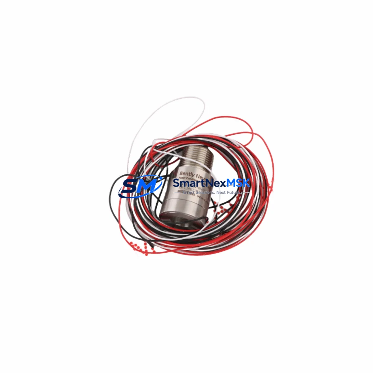
Bently Nevada 330101-00-40-05-02-05 3300 XL Spare: Precision Proximity Transducer for Industrial Downtime Control
The Bently Nevada 330101-00-40-05-02-05 is an original eddy-current proximity transducer engineered for the 3300 XL Series continuous vibration monitoring system. In rotating machinery protection — turbines, compressors, pumps, and gearboxes — this transducer is the primary sensing element that converts shaft displacement into a calibrated voltage signal. When this component degrades or fails, the entire vibration channel goes blind, exposing critical assets to undetected mechanical faults and unplanned shutdowns. Maintaining a verified spare on the shelf is not optional; it is a fundamental requirement of any serious predictive maintenance program.
This listing supplies a maintenance-ready, tested unit with full dimensional and electrical conformance to the original Bently Nevada specification. Each unit is inspected prior to dispatch and ships with a 12-month warranty covering manufacturing defects and electrical performance.
Spare Maintenance Table
| Parameter | Specification |
|---|---|
| Part Number | 330101-00-40-05-02-05 |
| Series | Bently Nevada 3300 XL |
| Sensor Type | Eddy-Current Proximity Transducer |
| Probe Length | 40 mm (active element) |
| Cable Length | 5 m (integral) |
| Connector | MIL-C-5015 (02-05 configuration) |
| Output Sensitivity | 7.87 V/mm (200 mV/mil) |
| Measurement Range | 0.25 – 2.25 mm (10 – 90 mil) |
| Supply Voltage | −24 VDC (nominal, via proximitor) |
| Operating Temperature | −35 °C to +120 °C |
| Ingress Protection | IP67 |
| Compatibility | 3300 XL Proximitor / Seismic Monitor, 3500 Series rack (with adapter) |
| Application | Radial vibration, axial position, differential expansion, eccentricity |
| Warranty | 12 Months from date of shipment |
| Shipping | Tested & inspected; ESD-safe packaging |
Maintenance Planning for Continuous Operation
When a maintenance or reliability engineer schedules replacement of the 330101-00-40-05-02-05 transducer, the work scope should extend beyond the probe itself. The 3300 XL measurement chain is a system: the transducer, the extension cable, and the proximitor module (such as the 330130-040-01-00 or 330180-X1-05 proximitor) must all be evaluated together. A degraded extension cable — particularly the 330130-series armored interconnect — can introduce impedance errors that mimic probe failure, so cable continuity and insulation resistance should be verified before condemning the transducer.
At the rack level, inspect the 3300/16-channel monitor or 3500/42M proximitor I/O module for input channel calibration drift. Recalibrate the channel after installing the new transducer using the standard gap voltage procedure (typically −10.0 VDC at 1.0 mm gap). If the machine train also uses 3300 XL seismic velocity sensors or 330425 accelerometers on the same bearing housing, verify that those channels remain within alarm setpoints after the transducer swap, as mechanical disturbance during installation can shift baseline readings.
For control cabinet integrity, check the 3300/05 power supply module output voltage (−24 VDC rail) and ripple. A noisy supply is a common root cause of erratic proximity readings that are misdiagnosed as transducer failure. Terminal blocks on the I/O barrier strip should be inspected for corrosion and re-torqued to specification. If the installation uses a Bently Nevada 3300/55 keyphasor module, confirm that the keyphasor gap voltage is within the −9.5 to −10.5 VDC window, as keyphasor signal integrity directly affects phase-referenced vibration analysis.
In legacy systems where the 3300 XL rack interfaces with a DCS historian via a 3500/92 communication gateway or Modbus RTU link, verify that the channel tag mapping is preserved after the replacement and that the DCS is receiving valid engineering-unit values before returning the machine to service. For sites running System 1 Evolution software, confirm that the transducer channel is re-enabled and that the gap voltage trend resets correctly in the asset health dashboard.
Site Replacement Workflow
Step 1 — Pre-work verification. Confirm the replacement unit part number matches the installed probe: 330101-00-40-05-02-05. Verify the cable length (5 m) and connector configuration (02-05) against the as-built drawing. Do not substitute a different cable-length variant without recalculating the system scale factor.
Step 2 — Isolation. Inhibit the vibration channel at the monitor rack to prevent spurious trips during removal. Document the current gap voltage and vibration baseline from the DCS or System 1 trend before disconnecting.
Step 3 — Removal. Disconnect the proximitor end of the extension cable. Unthread the probe from the bracket using the correct spanner — avoid gripping the cable. Inspect the probe tip for mechanical damage and the bracket bore for wear or contamination.
Step 4 — Installation. Thread the new 330101-00-40-05-02-05 probe to the correct gap (typically 1.0 mm / −10.0 VDC output). Reconnect the extension cable and proximitor. Restore channel inhibit and verify gap voltage at the monitor front panel or via System 1.
Step 5 — Functional test. Confirm vibration reading is within expected baseline ±10%. Check alarm and danger setpoints are active. Log the replacement in the CMMS with the new unit serial number and installation date to initiate the 12-month warranty period.
This workflow minimizes machine downtime to under two hours for a planned replacement and supports seamless backward compatibility with existing 3300 XL and 3500 Series infrastructure without firmware changes or rack reconfiguration.
Spare Parts Support FAQ
Q1: Is the 330101-00-40-05-02-05 a direct drop-in replacement for older 330101 variants?
A: The 330101-00-40-05-02-05 is dimensionally and electrically compatible with other 330101-series probes sharing the same cable length and connector suffix. However, always verify the full part number against the as-built drawing, as cable length and connector type variants affect system scale factor and physical fit. When in doubt, cross-reference the proximitor model number to confirm the matched-system configuration.
Q2: How do you verify the unit before shipment?
A: Each 330101-00-40-05-02-05 unit undergoes electrical continuity testing, insulation resistance measurement, and gap-voltage output verification against the 7.87 V/mm sensitivity specification prior to dispatch. Units are packed in ESD-safe, anti-static foam packaging to prevent transit damage. A test report is available upon request.
Q3: What is the recommended spare inventory strategy for this transducer?
A: For facilities operating more than four 3300 XL channels on critical rotating machinery, a minimum of two spare 330101-00-40-05-02-05 units is recommended. Pair each spare probe with a matched extension cable and a spare proximitor module to enable a complete channel swap without waiting for individual component sourcing. Rotate spares into service on a first-in, first-out basis and inspect stored units annually for connector corrosion.
Q4: What warranty coverage applies and how is a claim initiated?
A: All units carry a 12-month warranty from the date of shipment, covering manufacturing defects and electrical performance deviations from the published specification. To initiate a warranty claim, contact [email protected] with the order number, installation date, and a description of the observed fault. Replacement units are dispatched within 3 business days of claim approval.
© 2026 SMARTNEXMSK. All rights reserved.
Original Source: https://smartnexmsk.com
Contact: [email protected] | +86 18259474341