Bosch Rexroth VT-VSPD-1-22/V0/0-0-1 Retrofit-Ready Proportional Amplifier for Legacy Control Systems
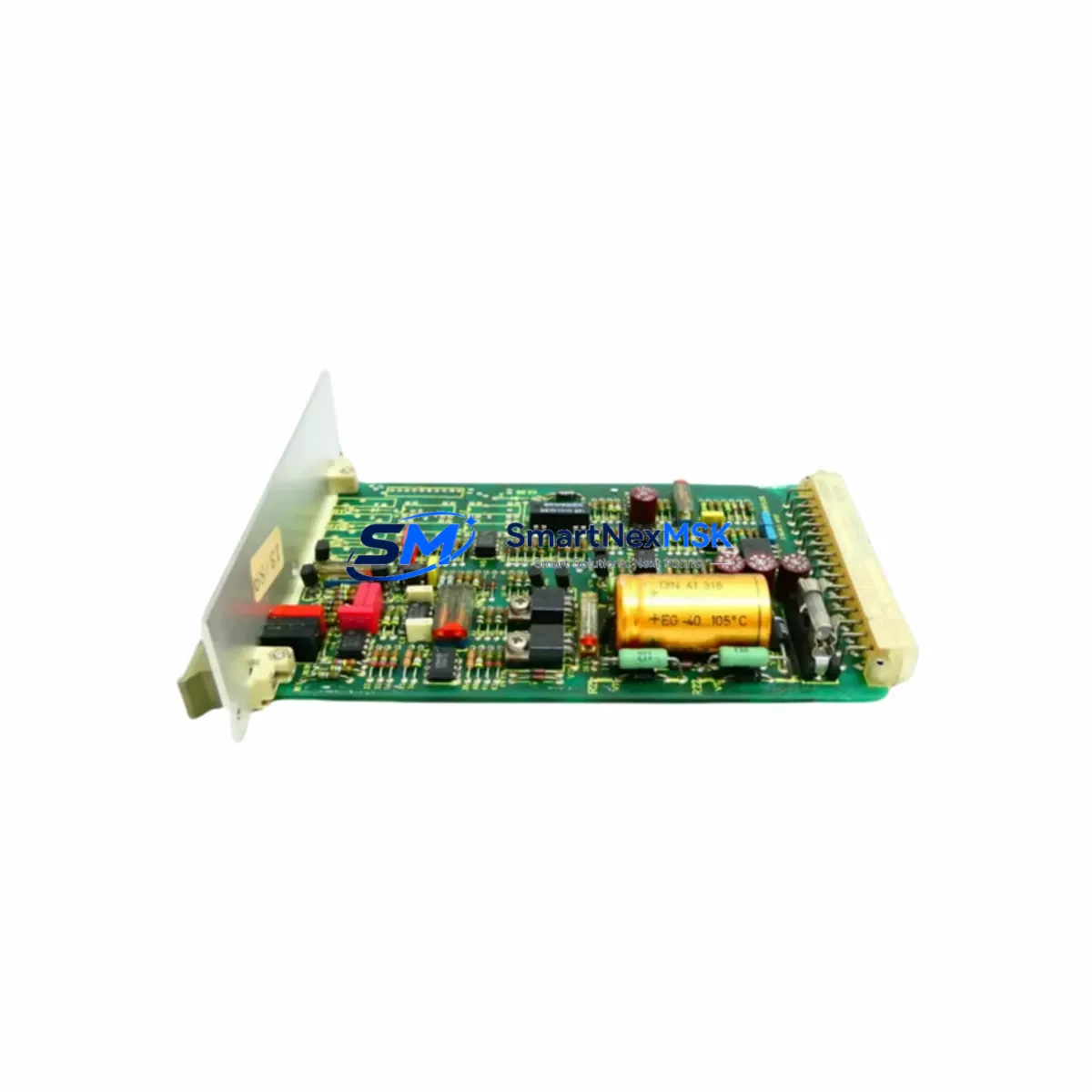
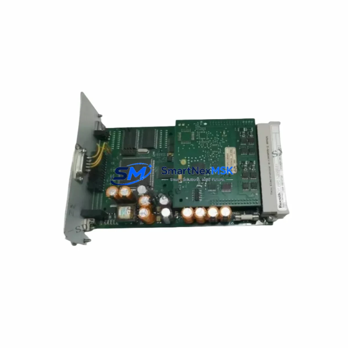
The Bosch Rexroth VT-VSPD-1-22/V0/0-0-1 is a high-performance proportional valve amplifier card engineered for precise electrohydraulic control in demanding industrial environments. As legacy hydraulic control systems reach end-of-life or face discontinued spare parts availability, the VT-VSPD-1-22/V0/0-0-1 serves as a proven retrofit solution — enabling engineers to restore full proportional control capability without redesigning the entire hydraulic circuit or replacing the valve body. This module is widely deployed in press systems, injection molding machines, metal forming lines, and continuous casting equipment where precise flow and pressure regulation is non-negotiable.
For facilities running older Bosch Rexroth VT-VSPD series amplifier cards, the VT-VSPD-1-22/V0/0-0-1 provides a direct-fit replacement path. The card interfaces with standard Rexroth proportional directional valves and pressure-reducing valves, maintaining the original command signal input (±10 V or 4–20 mA depending on configuration), enable logic, and ramp function parameters. Engineers replacing a failed or aging VT-VSPA2 or VT-VSPA1 amplifier should verify the valve coil resistance, command signal source, and enable wiring before substitution, as minor terminal mapping differences may apply between sub-variants.
Upgrade Compatibility Table
| Parameter | VT-VSPD-1-22/V0/0-0-1 | Notes / Retrofit Guidance |
|---|---|---|
| Supply Voltage | 24 V DC (±15%) | Verify existing PSU output; Rexroth VT-NE30 or equivalent 24 V DIN-rail PSU recommended |
| Command Signal Input | ±10 V / 4–20 mA (selectable) | Match PLC analog output card signal type; confirm AO module range before wiring |
| Enable Input | 24 V DC digital enable | Wire to PLC DO channel; confirm polarity with existing ladder logic |
| Output Stage | PWM current output to valve coil | Coil resistance must match; measure before installation |
| Ramp Function | Adjustable via onboard potentiometer | Record original ramp settings before card swap to preserve motion profiles |
| Mounting | DIN rail / sub-plate mount | Confirm rail spacing and sub-plate bolt pattern match existing cabinet layout |
| Communication | Analog (no fieldbus) | For fieldbus-integrated systems, pair with Rexroth VT-HNC100 or equivalent axis controller |
| Common Replacements | VT-VSPA2-1-1X, VT-VSPA1-1-1X | Cross-check terminal assignments; minor wiring adaptation may be required |
| Commissioning Tool | Rexroth IndraWorks / manual potentiometer | Use oscilloscope to verify valve response during initial commissioning |
| Warranty | 12 Months | Covers manufacturing defects; full functional test performed prior to shipment |
Retrofit Planning for Existing Automation Systems
A successful retrofit begins well before the VT-VSPD-1-22/V0/0-0-1 arrives on-site. Start by auditing the existing control cabinet: document the 24 V DC power rail capacity, confirm that the existing Rexroth VT-NE30 or third-party DIN-rail power supply can handle the additional current draw of the replacement amplifier card, and photograph all terminal connections on the outgoing card before disconnection. In multi-axis hydraulic systems, it is common to find the VT-VSPD-1-22/V0/0-0-1 installed alongside other Rexroth proportional amplifier cards such as the VT-VSPA2-1-1X for secondary axes, or paired with a VT-HNC100 axis controller for closed-loop position control applications.
For systems where the PLC analog output module — for example a Siemens SM 332 or an Allen-Bradley 1756-OF8 — drives the command signal, verify that the output range (±10 V or 4–20 mA) matches the VT-VSPD-1-22/V0/0-0-1 input configuration. If the original system used a 0–10 V unipolar signal, the amplifier’s internal offset and gain potentiometers must be adjusted accordingly during commissioning. In older installations, the command signal may be routed through a Rexroth VT-SWKA1-1X signal conditioning card; confirm whether this intermediate card is still functional or requires simultaneous replacement.
I/O wiring adaptation is often the most time-consuming part of a proportional amplifier retrofit. The enable signal, fault output, actual-value feedback (if used), and ramp-hold inputs must all be re-terminated to the new card’s terminal block. In cabinets where a Rexroth VT-VRPA2-1-1X valve position controller or a VT-HACD-1-1X hydraulic axis controller is present, confirm the inter-module signal routing before powering up. For systems using a Profibus DP or PROFINET gateway to communicate valve status back to the PLC, ensure the gateway module — such as a Rexroth VT-SSPA1-1-1X or equivalent — remains compatible with the updated amplifier card’s analog feedback signals.
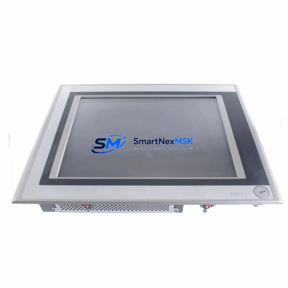
Where the original installation included a Rexroth HMI panel (e.g., IndraControl VEP or VPP series) displaying valve position or pressure setpoints, verify that the HMI tag addresses and scaling factors remain valid after the card swap. If the HMI reads actual-value feedback from the amplifier’s monitor output, re-calibrate the display scaling to match the new card’s output voltage range. This step is frequently overlooked and can cause misleading process displays even when the hydraulic system is functioning correctly.
Downtime Control During System Migration
Minimizing unplanned downtime during a proportional amplifier replacement requires a structured hot-swap protocol. Before removing the VT-VSPD-1-22/V0/0-0-1’s predecessor, place the hydraulic axis in a safe, de-energized position — typically by commanding the valve to its spring-centered neutral state via the PLC program. Back up the PLC program (including all analog scaling blocks, ramp function parameters, and safety interlock logic) to an offline storage device. If the system uses a Rexroth VT-HNC100 or IndraMotion MLC axis controller, export the axis parameter set using IndraWorks Engineering before any hardware changes.
With the axis safely parked, de-energize the 24 V DC supply rail feeding the amplifier card, disconnect the terminal block, and remove the card from its DIN rail or sub-plate mount. Install the VT-VSPD-1-22/V0/0-0-1, reconnect all terminals per the documented wiring photograph, and restore power. Before enabling the axis from the PLC, use a calibrated signal generator or the PLC’s manual jog function to apply a low-level command signal (e.g., ±1 V) and observe valve spool movement with a pressure gauge on the actuator port. This confirms correct wiring polarity and prevents uncontrolled actuator motion during first-time enable.
Once basic valve response is confirmed, restore the PLC program’s automatic mode and run the axis through its full travel range at reduced speed. Compare actual position or pressure feedback against the pre-retrofit baseline. Adjust the VT-VSPD-1-22/V0/0-0-1’s gain and ramp potentiometers as needed to match the original motion profile. For press or forming applications where force control is critical, perform a full load test cycle before releasing the machine to production. Total planned downtime for a single-axis amplifier swap using this protocol typically ranges from two to four hours, depending on cabinet accessibility and wiring complexity.
Retrofit Support FAQ
Q1: Is the VT-VSPD-1-22/V0/0-0-1 a direct drop-in replacement for the VT-VSPA2-1-1X?
In most applications, yes — both cards share the same functional role as proportional valve amplifiers for Rexroth directional and pressure-reducing valves. However, terminal pin assignments differ between sub-variants. Always compare the terminal diagrams from both datasheets and re-terminate wiring as needed. The enable input polarity and ramp-hold logic may also differ; verify against your existing PLC ladder logic before enabling the axis.
Q2: What commissioning steps are required after installation?
After physical installation and wiring, apply 24 V DC power and verify the card’s LED status indicators show no fault condition. Apply a low-level analog command signal from the PLC or a signal generator and confirm valve spool response using a pressure gauge or flow meter. Adjust the zero-offset, gain, and ramp potentiometers to match the original motion profile. For closed-loop position control systems using a VT-HNC100 axis controller, re-run the axis parameter identification routine in IndraWorks after card replacement.
Q3: How is compatibility with my existing valve verified before shipment?
Each VT-VSPD-1-22/V0/0-0-1 unit undergoes a full functional test on a hydraulic test bench prior to shipment, verifying command signal response, output current linearity, ramp function operation, and enable logic. To confirm compatibility with your specific valve model, provide the valve part number (e.g., 4WRKE, DBEM, or DREM series) and coil resistance specification. Our technical team will cross-reference the amplifier’s output stage parameters against your valve’s coil requirements before dispatch.
Q4: What does the 12-month warranty cover, and what is the return process?
The 12-month warranty covers all manufacturing defects, component failures, and functional deviations from the published datasheet specifications under normal operating conditions. It does not cover damage caused by incorrect wiring, overvoltage, or installation in environments exceeding the card’s rated temperature and humidity range. To initiate a warranty claim, contact our technical support team with the order number, a description of the fault symptom, and photographs of the installation. Replacement or repair is typically completed within 5–10 business days of receiving the returned unit.
© 2026 SMARTNEXMSK. All rights reserved.
Original Source: https://smartnexmsk.com
Contact: [email protected] | +86 18259474341