Control Techniques MP210A4R Spare for Mentor MP Automation: Spare Replacement & Industrial Downtime Risk Control
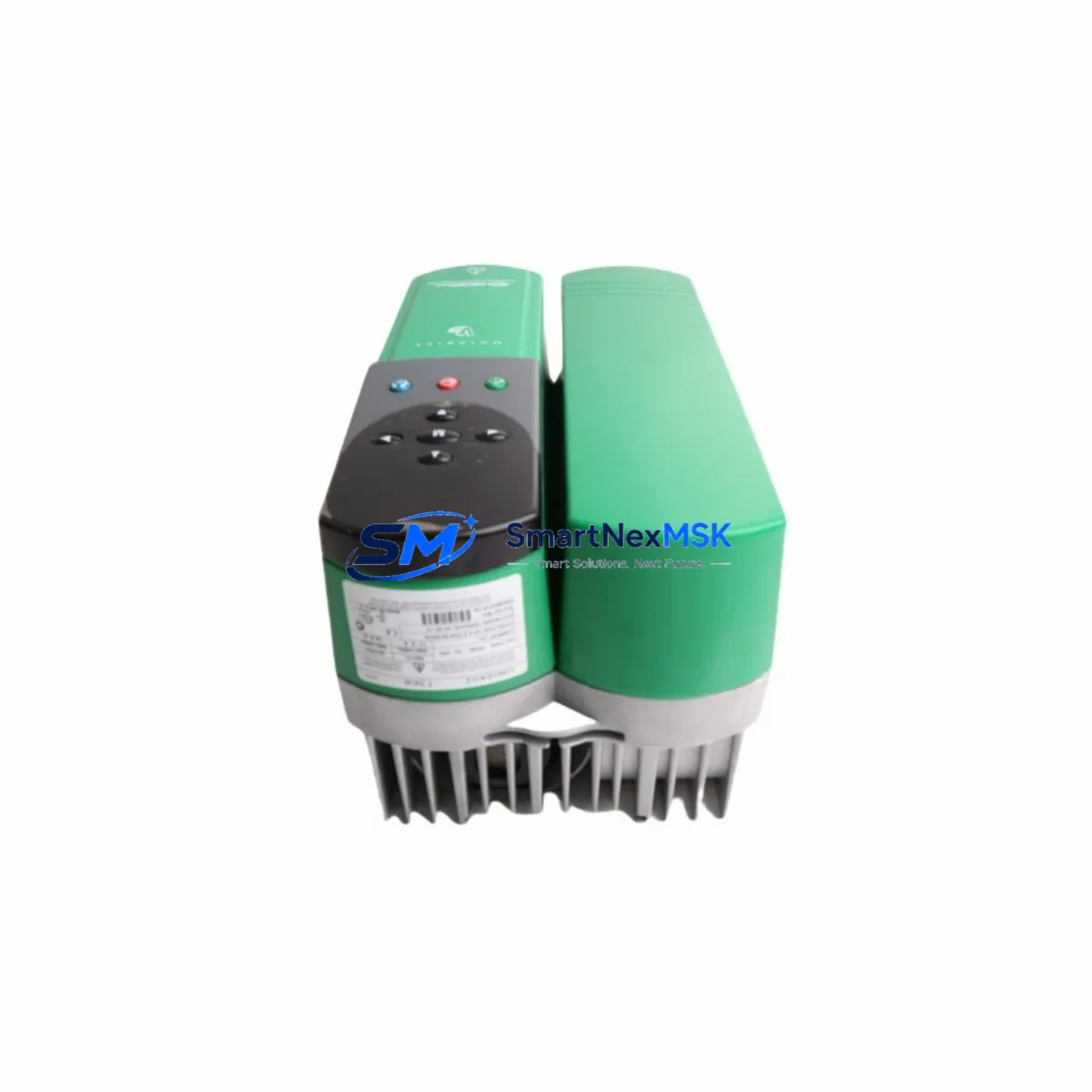
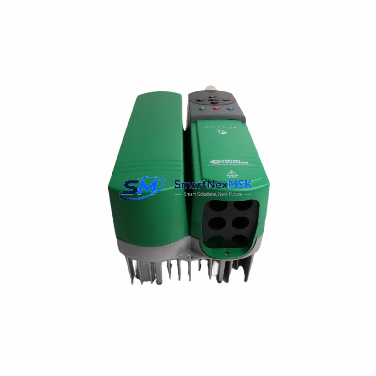
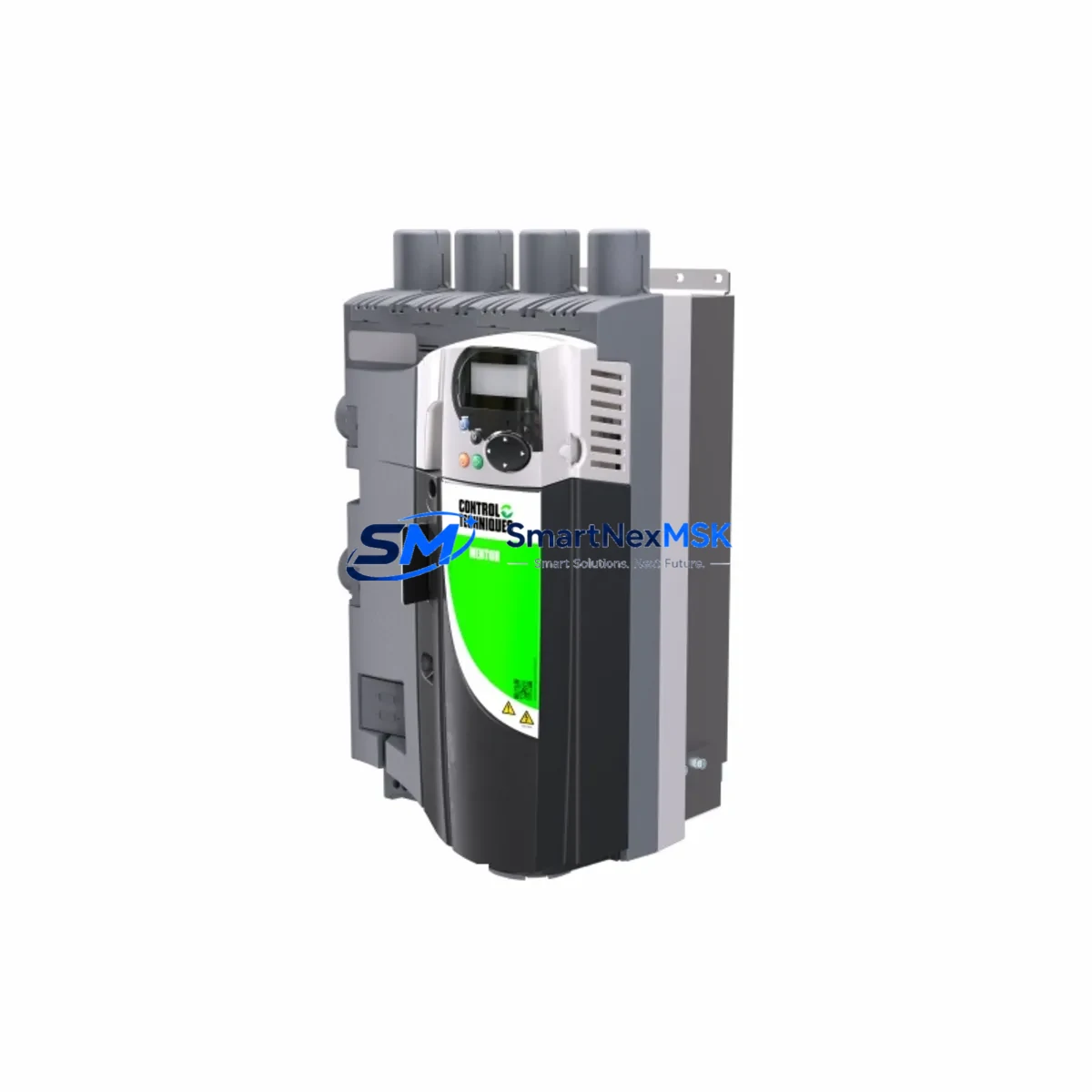
The Control Techniques MP210A4R is a 210A four-quadrant regenerative DC drive from the Mentor MP series, engineered for demanding industrial automation environments including metal processing, paper mills, extruders, winding machines, and heavy-duty conveyor systems. As a maintenance-ready original spare, the MP210A4R enables rapid field replacement of failed or degraded drives, minimizing unplanned downtime and protecting production continuity in both legacy and active control architectures.
For maintenance engineers managing aging DC drive systems, sourcing a verified original MP210A4R is critical. Counterfeit or incompatible substitutes risk motor damage, control loop instability, and cascading failures across the drive cabinet. SMARTNEXMSK supplies tested, original-specification MP210A4R units with a 12-month warranty, full functional verification prior to dispatch, and long-term stock availability to support planned maintenance cycles and emergency replacement scenarios alike.
Spare Maintenance Table
| Parameter | Specification |
|---|---|
| Part Number / SKU | MP210A4R |
| Brand | Control Techniques |
| Series | Mentor MP |
| Product Type | Regenerative DC Drive (4-Quadrant) |
| Output Current | 210A continuous |
| Supply Voltage | 380–480V AC, 3-phase (±10%) |
| DC Output Voltage | Up to 500V DC (armature) |
| Control Mode | Speed & Torque (closed-loop, open-loop) |
| Communication | RS485 / Optional fieldbus (PROFIBUS, DeviceNet, EtherNet/IP via SI module) |
| I/O | Analog & Digital I/O configurable via parameters |
| Protection Class | IP20 (panel mount) |
| Operating Temperature | 0°C to +40°C (derating above 40°C) |
| Cooling | Forced air (internal fan) |
| Origin | United Kingdom |
| Compatibility | Direct replacement for Mentor MP 210A frame; backward compatible with Mentor II 210A applications |
| Installation | DIN rail / panel mount; standard Mentor MP wiring footprint |
| Warranty | 12 Months (SMARTNEXMSK) |
| Pre-shipment Testing | Full functional verification, parameter restore, load simulation |
| Availability | Long-term stock; emergency dispatch supported |
Maintenance Planning for Continuous Operation
When replacing an MP210A4R in the field, a thorough inspection of the surrounding drive cabinet is essential to prevent repeat failures and ensure system stability. Maintenance engineers should treat the drive replacement as an opportunity for a full electrical health check of the associated control loop.
Begin by verifying the incoming AC supply — check for voltage imbalance, harmonic distortion, and the condition of the upstream line reactor or AC choke, which protects the drive’s input rectifier from supply transients. Inspect the DC bus fuses and semiconductor fuses (fast-acting HRC types rated for DC drive duty) for signs of thermal stress or prior operation near rated current. A blown fuse upstream of the previous drive is a common root cause that, if overlooked, will destroy the replacement unit.
Next, inspect the field supply unit — the Mentor MP series uses a separate field controller, and the MP-FIELDCONTROL or equivalent field regulator board should be checked for correct output voltage and ripple. A degraded field supply causes motor overheating and poor speed regulation, symptoms often misattributed to the drive itself.
Review the armature feedback circuit: check the condition of the armature voltage feedback wiring, the tachogenerator or encoder feedback device, and the signal cable shielding. Noise on the speed feedback signal is a frequent cause of instability in regenerative DC drives. If the system uses a pulse encoder for closed-loop speed control, verify encoder supply voltage and signal integrity at the drive’s encoder input terminals.
Inspect all control terminal wiring — analog reference inputs (0–10V or 4–20mA), digital enable signals, and relay output wiring. Corroded or loose terminals on the control PCB connector strip are a common source of intermittent faults. Check the condition of the 24V DC auxiliary supply feeding the control logic; an unstable auxiliary supply can cause spurious trips and parameter corruption.
For systems using fieldbus communication, verify the SI-PROFIBUS, SI-DeviceNet, or SI-EtherNet/IP option module is correctly seated and that the network termination resistors are in place. Communication module faults are often masked by drive replacement if not explicitly checked. Similarly, if the drive interfaces with a Unidrive SP or Commander SK master drive in a coordinated multi-drive system, verify the inter-drive communication links remain intact after the swap.
Finally, inspect the motor thermistor circuit and the motor protection relay wiring. Confirm that the motor’s armature resistance and inductance values are within the expected range before commissioning the replacement MP210A4R, and restore all drive parameters from a saved parameter file or the site commissioning record before enabling the drive under load.
Site Replacement Workflow
The MP210A4R is a direct form-fit-function replacement for any Mentor MP 210A frame drive. The replacement procedure is designed to minimize downtime and maintain system compatibility:
1. Isolation & Safety: Isolate the drive from the AC supply and DC bus. Verify zero voltage on the DC bus capacitors using a calibrated meter before touching internal components. Lock out / tag out (LOTO) the upstream isolator.
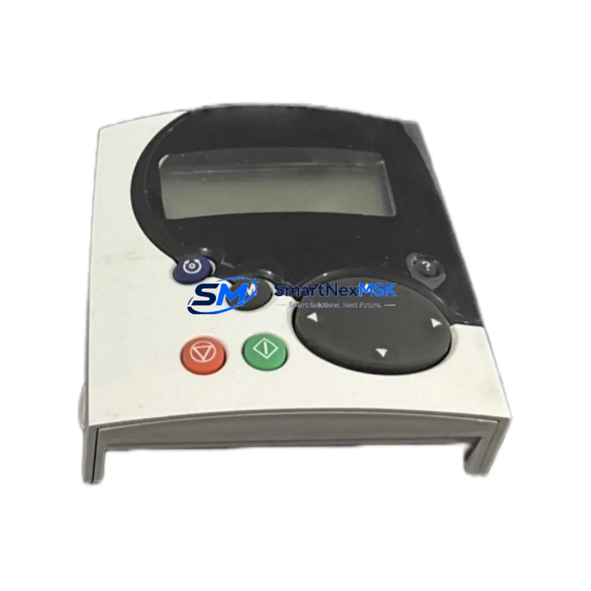
2. Parameter Backup: If the existing drive is still partially functional, upload the full parameter set via the Mentor MP keypad or CTSoft / SyPTLite commissioning software before removal. Store the parameter file with the site maintenance record.
3. Mechanical Removal: Disconnect armature, field, and AC supply cables. Label all terminals before removal. The MP210A4R uses the standard Mentor MP mechanical frame — mounting hole pattern and cable entry points are identical across the 210A frame variants, eliminating the need for panel modifications.
4. Installation of Replacement Unit: Mount the new MP210A4R, reconnect all cables per the original wiring diagram, and verify terminal torque settings per the Mentor MP installation guide. Reconnect the field supply, encoder/tacho feedback, and control wiring.
5. Parameter Restore & Commissioning: Download the saved parameter file to the replacement drive. Verify motor nameplate data (armature voltage, rated current, field voltage) against drive parameters. Perform a no-load run before applying full production load. Monitor drive diagnostics for the first 30 minutes of operation.
This workflow supports rapid changeover — experienced engineers typically complete an MP210A4R swap in under two hours, significantly reducing mean time to repair (MTTR) compared to sourcing and commissioning an unfamiliar alternative drive platform.
Spare Parts Support FAQ
Q1: What is the warranty coverage for the MP210A4R supplied by SMARTNEXMSK?
All MP210A4R units supplied by SMARTNEXMSK carry a 12-month warranty covering manufacturing defects and functional failures under normal operating conditions. Each unit undergoes full functional verification and load simulation testing prior to dispatch. Warranty claims are supported with direct technical assistance and replacement dispatch.
Q2: Can the MP210A4R replace an older Mentor II 210A drive without panel modifications?
In most cases, yes. The Mentor MP series was designed with backward compatibility in mind for the Mentor II platform. The MP210A4R shares a similar mechanical footprint and wiring convention with the Mentor II 210A frame. However, parameter mapping and fieldbus configuration will require re-commissioning. SMARTNEXMSK recommends reviewing the Mentor MP migration guide and consulting your site commissioning records before proceeding.
Q3: How does SMARTNEXMSK verify stock authenticity and functional condition before shipping?
Every MP210A4R unit in SMARTNEXMSK inventory is inspected for physical condition, tested for correct power stage operation, and verified against original Control Techniques specifications. Units are tested under simulated load conditions where possible. A test report is available upon request. We do not supply refurbished units represented as new — condition is clearly stated at the time of quotation.
Q4: What is the recommended spare parts strategy for sites running Mentor MP DC drive systems?
For sites with multiple Mentor MP drives, we recommend maintaining at least one MP210A4R (or the appropriate frame size) as a cold standby spare. Given the long lead times for new DC drive procurement and the criticality of DC drive applications (typically connected to main production motors), a local spare eliminates the risk of extended downtime. SMARTNEXMSK supports long-term supply agreements and can reserve stock for scheduled maintenance windows.
© 2026 SMARTNEXMSK. All rights reserved.
Original Source: https://smartnexmsk.com
Contact: [email protected] | +86 18259474341