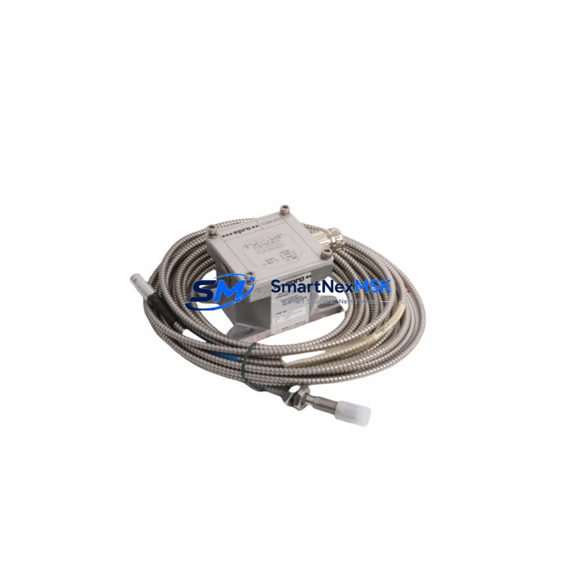
EPRO PR6423/010-140 CON011 Retrofit-Ready Eddy Current Proximity Sensor for PR6423 Series Control Systems
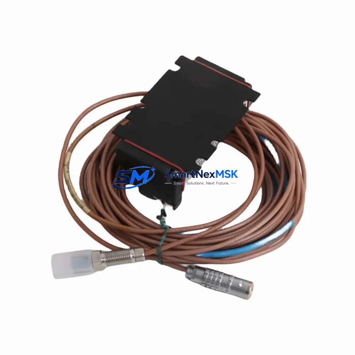
The EPRO PR6423/010-140 CON011 is a high-precision eddy current proximity sensor engineered for shaft vibration and displacement monitoring in rotating machinery. Designed as a direct retrofit replacement within the PR6423 series ecosystem, this sensor supports seamless integration into existing Bently Nevada-compatible and EPRO-native monitoring architectures without requiring structural modifications to the control cabinet or sensor mounting bracket. Whether you are replacing a discontinued unit, recovering from an unplanned shutdown, or executing a planned upgrade of your condition monitoring infrastructure, the PR6423/010-140 CON011 delivers the dimensional accuracy, signal linearity, and environmental resilience demanded by industrial turbine, compressor, and pump applications.
The PR6423/010-140 CON011 operates as part of the EPRO PR6423 series, which pairs with the CON011 extension cable and the PR9268 series signal conditioning drivers to form a complete proximity measurement chain. When retrofitting this sensor into an existing installation, engineers must verify the total system cable length — the combined length of the sensor’s integral cable and the CON011 extension must fall within the calibrated range specified for the PR9268/11 or PR9268/12 driver in use. Mismatched cable lengths are the most common source of calibration offset errors during retrofit commissioning, and this verification step should be completed before the system is powered on.
Terminal wiring compatibility is a critical checkpoint during any PR6423 series replacement. The CON011 extension cable uses a standard coaxial connector interface at both the sensor end and the driver end. Before disconnecting the legacy sensor, document the existing cable routing, connector orientation, and any ferrite bead or shielding arrangements in the junction box. The PR6423/010-140 CON011 uses the same connector standard as earlier PR6423 variants, so no adapter is required, but the shield grounding point at the driver input terminal — typically on the PR9268 series driver card — must be verified to be single-point grounded to avoid ground loop interference in the 4–20 mA or voltage output signal chain.
Backplane and rack compatibility is straightforward for installations using the EPRO MMS 6000 or MMS 3000 series monitoring racks. The PR6423/010-140 CON011 integrates with the same driver slots occupied by its predecessors, and no firmware update to the rack controller is required for a like-for-like sensor swap. However, if the retrofit is part of a broader system upgrade — for example, migrating from an MMS 3000 rack to an MMS 6000 rack — the module address assignments and channel configuration in the monitoring software must be re-mapped. This is typically performed through the EPRO System Manager configuration tool, where each sensor channel is assigned a tag name, engineering unit, and alarm threshold that must match the values previously configured for the replaced sensor.
HMI screen updates are often overlooked during sensor retrofits. If the plant DCS or SCADA system displays vibration trend data sourced from the PR6423 channel, the tag binding in the HMI project must be verified after the replacement. In Siemens TIA Portal-based HMI projects or Rockwell FactoryTalk View configurations, the analog input tag linked to the proximity sensor channel should be confirmed against the new channel address before the system is returned to service. Similarly, if the monitoring rack communicates over Modbus RTU or PROFIBUS DP to a Siemens S7-300 or S7-400 PLC, the register map for the vibration channel should be cross-checked to ensure no address shift occurred during the rack reconfiguration.
For installations where the PR6423/010-140 CON011 is replacing a sensor in a legacy Bently Nevada 3300 series or 7200 series proximity system, a full calibration gap voltage check is mandatory. The target gap voltage for the PR6423 series at the nominal 2 mm installation gap is typically −10 VDC, but this must be confirmed against the specific driver’s calibration curve. Use a non-conductive feeler gauge to set the physical gap, then measure the driver output voltage with a calibrated multimeter before connecting the signal to the monitoring rack. This step prevents false alarm trips and ensures the vibration baseline recorded in the historian is accurate from the first moment of operation.
Communication link integrity between the monitoring rack and the plant control system should be validated as part of the commissioning checklist. If the MMS 6000 rack uses an Ethernet/IP or OPC DA interface to report to the plant DCS, a live data comparison between the rack’s local display and the DCS historian tag should be performed for at least one full machine start-up cycle. Any discrepancy greater than 5% of full scale warrants investigation of the signal conditioning chain, including the PR9268 driver gain setting and the analog input card scaling in the DCS I/O module.
Inventory availability for the PR6423/010-140 CON011 is maintained to support both emergency replacement and planned maintenance schedules. Units are shipped with a 12-month warranty covering manufacturing defects and calibration accuracy. Each unit undergoes pre-shipment functional testing, including gap voltage linearity verification across the full measurement range, before dispatch. Customers requiring expedited delivery for unplanned outage recovery can contact the sales team directly for same-day or next-day shipping arrangements.
Upgrade Compatibility Table
| Parameter | PR6423/010-140 CON011 | Notes / Retrofit Guidance |
|---|---|---|
| Sensor Series | EPRO PR6423 | Compatible with all PR6423 series driver/cable combinations |
| Extension Cable | CON011 | Total cable length must match PR9268 driver calibration range |
| Signal Conditioning Driver | PR9268/11, PR9268/12 | Verify driver gain setting after sensor replacement |
| Connector Interface | Coaxial (standard PR6423) | No adapter required; verify shield grounding at driver input |
| Nominal Installation Gap | 2 mm (−10 VDC output) | Confirm gap voltage with calibrated multimeter before commissioning |
| Rack Compatibility | MMS 6000, MMS 3000 | Re-map channel addresses if migrating between rack generations |
| Communication Protocol | Modbus RTU, PROFIBUS DP, Ethernet/IP, OPC DA | Verify register map and tag binding in DCS/SCADA after replacement |
| Legacy System Compatibility | Bently Nevada 3300, 7200 series | Full calibration gap voltage check mandatory for cross-brand retrofit |
| HMI Integration | Siemens TIA Portal, Rockwell FactoryTalk View | Verify analog input tag binding after channel reconfiguration |
| Warranty | 12 Months | Covers manufacturing defects and calibration accuracy; pre-shipment tested |
Retrofit Planning for Existing Automation Systems
A successful PR6423/010-140 CON011 retrofit begins with a thorough audit of the existing measurement chain. Start by identifying all components in the signal path: the sensor itself, the CON011 extension cable, the PR9268 series driver card seated in the MMS 6000 or MMS 3000 monitoring rack, and the analog input module in the plant PLC or DCS — commonly a Siemens S7-300 SM 331 analog input card or an equivalent Rockwell 1756-IF16 ControlLogix analog input module. Each of these components has a defined role in the measurement chain, and a change at the sensor level can propagate calibration offsets through the entire signal path if not properly managed.
Power supply capacity in the control cabinet must be verified before installation. The PR6423 series sensor draws its operating power from the PR9268 driver, which in turn is powered by the rack’s internal 24 VDC bus. If the retrofit is accompanied by the addition of new I/O modules — such as a PR6424 series sensor for an adjacent measurement point, or a new PR9376 series relay output module for alarm annunciation — the total current draw on the 24 VDC rail must be recalculated to ensure the existing power supply module, typically a PR9376 or equivalent rack power supply, is not overloaded. A margin of at least 20% above the calculated load is recommended for industrial reliability.
Terminal block wiring in the junction box between the sensor cable and the extension cable should be inspected for corrosion, loose ferrules, and correct torque on screw terminals. In high-vibration environments, self-loosening of terminal screws is a known failure mode, and the use of spring-clamp terminal blocks — such as those in the Phoenix Contact PTFIX or Weidmüller Klippon series — is recommended for any junction box exposed to continuous mechanical vibration. The shield drain wire from the CON011 extension cable must be terminated at a single grounding point; double-grounding the shield introduces a ground loop that manifests as a 50 Hz or 60 Hz noise component on the proximity signal, which can trigger false high-vibration alarms in the monitoring rack.
Module address configuration in the MMS 6000 rack is performed through the EPRO System Manager software. Each sensor channel is assigned a slot address, a measurement type (radial vibration, axial position, or speed), and a set of alarm thresholds (Alert and Danger levels). When replacing a PR6423 sensor, the existing channel configuration can be exported as an XML backup before the replacement and re-imported after commissioning to restore all alarm setpoints and tag names without manual re-entry. This approach eliminates transcription errors and reduces the risk of incorrect alarm threshold settings that could compromise machinery protection during the post-retrofit run-up period.
Program compatibility in the plant PLC should be verified by reviewing the analog input scaling block associated with the proximity sensor channel. In a Siemens S7-300 or S7-400 program, this is typically implemented as a FC105 SCALE function block that converts the raw analog input value (0–27648 counts) to an engineering unit value in micrometers or mils. The scaling parameters — lower limit, upper limit, and bipolar flag — must match the output range of the PR9268 driver for the specific sensor and cable combination in use. If the driver output range has changed due to a cable length adjustment during the retrofit, the FC105 scaling parameters must be updated accordingly in the PLC program before the system is returned to automatic control.
Downtime Control During System Migration
Minimizing downtime during a PR6423/010-140 CON011 replacement requires a structured pre-outage preparation protocol. Before the maintenance window begins, the replacement sensor should be bench-tested using a portable PR9268 driver and a reference target to verify that the gap voltage at 2 mm matches the expected −10 VDC within the specified tolerance. This pre-verification step eliminates the risk of discovering a faulty replacement unit after the machine has already been shut down and the original sensor removed.
The original PLC program logic — including all analog scaling blocks, alarm interlock rungs, and historian tag configurations — should be backed up to a secure offline location before any hardware changes are made. In Siemens Step 7 or TIA Portal environments, this means uploading the current online program to the programming device and saving a timestamped archive. In Rockwell Studio 5000 environments, an ACD file backup should be saved and verified for completeness. These backups serve as the recovery baseline if the commissioning of the new sensor reveals unexpected signal behavior that requires program modification.
During the physical sensor swap, the machine should be in a confirmed safe state with the main drive isolated and locked out per the site LOTO procedure. The CON011 extension cable should be disconnected at the junction box before the sensor is removed from the bearing housing, to avoid mechanical stress on the cable connector. After the new PR6423/010-140 CON011 is installed and the gap set to the nominal 2 mm, the extension cable is reconnected and the driver output voltage is measured before the monitoring rack is powered on. Only after the gap voltage is confirmed within specification should the rack be energized and the DCS or SCADA system reconnected to the live channel.
Post-replacement, a controlled machine start-up with continuous vibration trend monitoring is recommended for the first 30 minutes of operation. The vibration baseline recorded during this run-up should be compared against the historical baseline stored in the plant historian to confirm that the new sensor is tracking correctly. Any deviation greater than 10% of the historical baseline at the same operating speed warrants a re-check of the installation gap, cable length, and driver calibration before the machine is returned to full production load.
By following this structured replacement protocol, most PR6423/010-140 CON011 retrofits can be completed within a 2–4 hour maintenance window, preserving the original program logic, alarm configurations, and historian tag structure while restoring full machinery protection capability.
Retrofit Support FAQ
Q1: Is the PR6423/010-140 CON011 a direct drop-in replacement for earlier PR6423 variants?
Yes, the PR6423/010-140 CON011 is dimensionally and electrically compatible with earlier PR6423 series sensors using the CON011 extension cable. The connector interface, thread size, and driver compatibility are unchanged. However, the total cable length (sensor integral cable + CON011 extension) must be verified against the PR9268 driver’s calibration range, as different CON011 lengths are available and the driver is calibrated for a specific total length.
Q2: What commissioning steps are required after installation?
After physical installation, set the sensor gap to 2 mm using a non-conductive feeler gauge and measure the PR9268 driver output voltage with a calibrated multimeter. Confirm the gap voltage is within the specified tolerance (typically −10 VDC ± 0.5 VDC). Then verify the analog input scaling in the PLC program, confirm the DCS/SCADA tag binding, and perform a controlled machine start-up with vibration trend monitoring for the first 30 minutes of operation.
Q3: Can this sensor be used to replace a Bently Nevada 3300 XL 8 mm proximity sensor?
The PR6423/010-140 CON011 is an EPRO-series sensor and is not a direct electrical replacement for Bently Nevada 3300 XL series sensors, which use a different driver and calibration standard. Cross-brand retrofits require a full recalibration of the measurement chain using the EPRO PR9268 driver and a new gap voltage verification. The monitoring rack channel configuration must also be updated to reflect the EPRO sensor’s output characteristics. Contact our technical team for a cross-brand retrofit assessment before proceeding.
Q4: What does the 12-month warranty cover, and how is it validated?
The 12-month warranty covers manufacturing defects and calibration accuracy from the date of shipment. Each PR6423/010-140 CON011 unit undergoes pre-shipment functional testing, including gap voltage linearity verification across the full measurement range, and ships with a test certificate. Warranty claims require the original order reference and a description of the observed fault. Units that have been physically damaged, modified, or installed outside the specified environmental ratings are not covered under the standard warranty.
© 2026 SMARTNEXMSK. All rights reserved.
Original Source: https://smartnexmsk.com
Contact: [email protected] | +86 18259474341