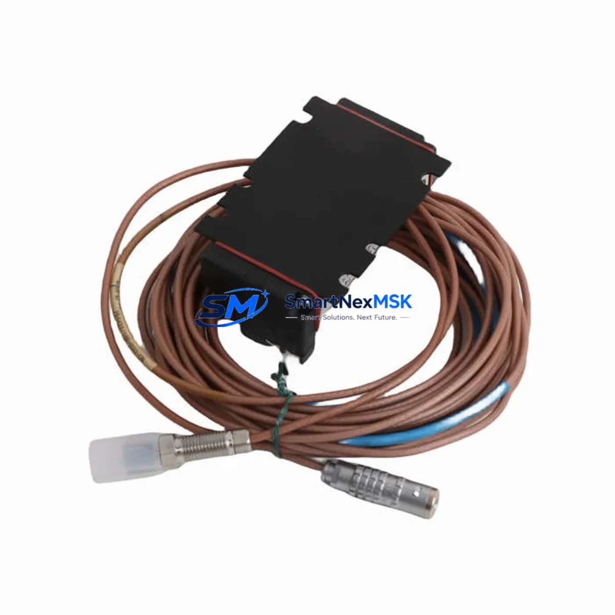
EPRO PR6423/10R-141 CON031 Retrofit-Ready Eddy Current Proximity Sensor for PR6423 Series Control Systems
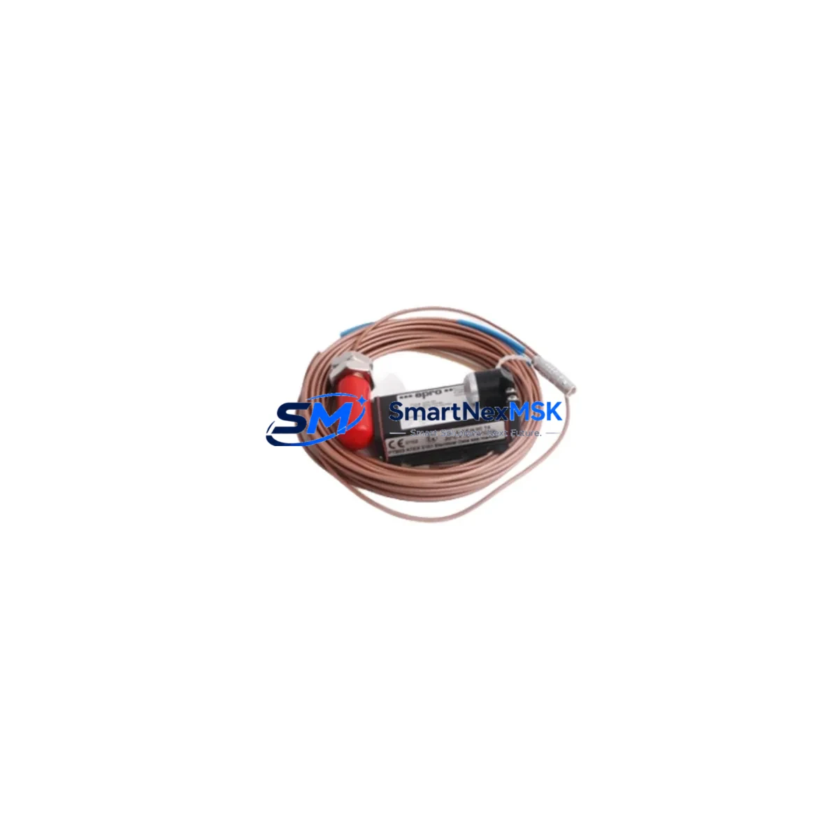
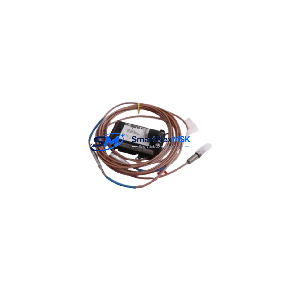
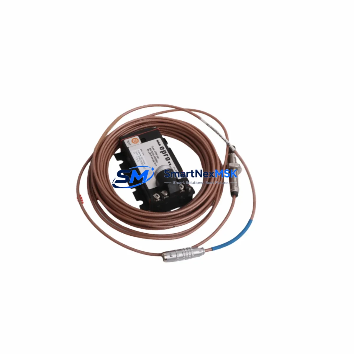
The EPRO PR6423/10R-141 CON031 is a high-precision eddy current proximity sensor engineered for seamless integration into existing PR6423 Series vibration monitoring and machinery protection systems. Designed with retrofit compatibility as a core specification, this sensor enables maintenance engineers and automation teams to replace discontinued or end-of-life proximity transducers without requiring full system redesign, panel rewiring, or PLC reprogramming. Whether you are upgrading an aging turbine protection rack, restoring a legacy condition monitoring loop, or migrating from an obsolete Bently Nevada 3300 Series installation, the PR6423/10R-141 CON031 delivers the dimensional accuracy, signal linearity, and connector compatibility required for a controlled, low-risk cutover.
In industrial retrofit projects, the proximity sensor is rarely the only component under review. Engineers replacing the PR6423/10R-141 CON031 typically also evaluate the companion EPRO CON021 and CON041 signal conditioning modules, the PR6423 extension cable assemblies, and the PR9268 series driver units that interface with the monitoring rack. Where the existing installation uses a Bently Nevada 3500/42M proximity monitor or a 3300 XL 8mm transducer system, the PR6423/10R-141 CON031 provides a technically validated cross-reference path, subject to gap voltage calibration and sensitivity verification during commissioning. Installations running EPRO MMS 6350 or MMS 6110 machinery management systems will find the PR6423 series fully supported within those monitoring architectures.
Before finalising a retrofit bill of materials, engineers should confirm the following parameters against the existing installation: probe tip diameter and target material compatibility, cable length and extension cable impedance matching, driver supply voltage (typically –24 VDC), output sensitivity (standard 7.87 V/mm or 200 mV/mil), and the connector type at the junction box or terminal strip. The CON031 connector variant is specified for this listing; installations using CON021 or CON041 terminations require the corresponding part number. Confirm the gap setting range against the target shaft diameter and material before ordering.
Upgrade Compatibility Table
| Parameter | PR6423/10R-141 CON031 | Notes / Retrofit Guidance |
|---|---|---|
| Probe Tip Diameter | 10 mm | Verify target bore clearance before installation |
| Cable Length | 141 cm (probe + integral cable) | Match or use PR6423 extension cable to reach driver |
| Connector Type | CON031 | Incompatible with CON021/CON041 sockets without adapter |
| Supply Voltage | –24 VDC (nominal) | Confirm driver output; do not substitute with –18 VDC drivers |
| Output Sensitivity | 7.87 V/mm (200 mV/mil) | Recalibrate monitor alert/danger setpoints after swap |
| Target Material | Steel / Stainless Steel | Non-ferrous targets require sensitivity correction factor |
| Communication / Signal | Analogue (4–20 mA / voltage) | Compatible with MMS 6350, MMS 6110, Bently 3500 racks |
| Mounting Thread | M10 × 1 | Reuse existing probe holder if thread condition is acceptable |
| Replacement Cross-Reference | Bently Nevada 330101 / 3300 XL 8mm (with recalibration) | Gap voltage and sensitivity differ; full commissioning required |
| Warranty | 12 Months | Covers manufacturing defects; excludes installation damage |
Retrofit Planning for Existing Automation Systems
A successful PR6423/10R-141 CON031 retrofit begins well before the maintenance window opens. The first step is a full audit of the existing proximity transducer loop: document the probe serial number, cable routing, junction box terminal assignments, driver module location within the monitoring rack, and the current gap voltage reading at the driver output. This baseline data becomes the acceptance criterion for the replacement unit.
In most PR6423 Series installations, the driver module — typically a PR9268/20S or PR9268/60S driver — is mounted in a dedicated slot within the machinery protection rack. Confirm that the driver is functioning correctly before attributing a fault to the probe itself; a failed driver will produce identical symptoms to a failed probe. Where the rack also houses EPRO PR6426 velocity transducers or PR9376 acceleration transducers, take the opportunity to inspect those signal cables and terminal connections during the same outage.
For installations migrating from legacy Bently Nevada 3300 XL or 330101-00-06-10-02-00 proximity systems to the EPRO PR6423 platform, the key differences to manage are the gap voltage range (Bently systems typically operate at –10.0 V nominal gap; EPRO systems at –10.0 V to –12.0 V depending on target material and gap distance) and the connector interface at the driver input. A PR6423 series extension cable with the correct CON031 termination must be routed from the probe to the driver; reusing Bently extension cables is not recommended without impedance verification.
Where the control system includes a Siemens S7-300 or S7-400 PLC receiving analogue inputs from the machinery protection rack, confirm that the 4–20 mA or voltage signal scaling in the PLC program matches the new sensor’s sensitivity. If the HMI — whether a Siemens WinCC panel or a third-party SCADA display — shows vibration in engineering units (µm or mils), the scaling factor in the analogue input block must be updated to reflect the PR6423/10R-141 CON031 output curve. Failure to update this scaling will result in incorrect vibration readings without triggering any hardware fault alarm.
Terminal strip wiring for the PR6423/10R-141 CON031 follows the standard EPRO colour code: the shield drain wire must be grounded at the driver end only (single-point grounding) to prevent ground loop interference. In older installations where the shield was grounded at both ends, removing the probe-end ground connection is a mandatory step before commissioning the replacement unit. Document the as-left terminal assignments and update the panel wiring diagram before closing the control cabinet.
Downtime Control During System Migration
Minimising unplanned downtime during a proximity sensor replacement requires a structured pre-outage preparation protocol. Before the maintenance window, pre-configure the replacement PR6423/10R-141 CON031 on a bench test rig: connect it to a spare PR9268 driver, set the gap to the nominal value using a non-ferrous spacer gauge, and verify the output voltage is within the specified range. Record the bench gap voltage as the baseline for field commissioning.
During the outage, follow a defined sequence: isolate the driver supply voltage, disconnect the existing probe cable at the junction box (do not cut — preserve the original wiring for reference), remove the probe from the holder, install the PR6423/10R-141 CON031, reconnect the extension cable with the CON031 connector, restore driver power, and measure the gap voltage before releasing the machine for rotation. The entire swap, if pre-staged, can be completed within a 30–45 minute window on a well-documented installation.
To protect the original PLC program logic during the migration, place the affected analogue input channel in manual override or simulation mode within the Siemens S7 or equivalent control platform before disconnecting the sensor. This prevents spurious vibration alarms or emergency shutdowns triggered by the open-circuit signal during the swap interval. Restore the channel to automatic mode only after the gap voltage has been verified and the machine is back on turning gear. Maintain a written commissioning record — gap voltage, output voltage, alarm setpoint confirmation, and technician sign-off — as part of the retrofit documentation package.
Retrofit Support FAQ
Q1: Is the PR6423/10R-141 CON031 a direct drop-in replacement for the Bently Nevada 330101 proximity probe?
The PR6423/10R-141 CON031 is a functional equivalent for many Bently Nevada 330101 applications, but it is not a plug-and-play replacement. The connector interface (CON031 vs. Bently standard BNC/coax), gap voltage calibration, and sensitivity curve must all be verified and adjusted during commissioning. A full calibration check against the monitoring rack’s alert and danger setpoints is mandatory before returning the machine to service.
Q2: What wiring changes are required when replacing an existing PR6423 probe with the CON031 variant?
If the existing installation uses a CON031-terminated extension cable, no wiring changes are required at the junction box or driver input. If the existing cable uses a CON021 or CON041 termination, the extension cable must be replaced with a CON031-compatible assembly. Always verify single-point shield grounding at the driver end and update the panel wiring diagram to reflect the as-left configuration.
Q3: How is the gap voltage verified after installing the PR6423/10R-141 CON031?
With the driver powered and the probe installed at the nominal gap distance (typically 1.0–1.5 mm for a 10 mm probe on a steel target), measure the DC voltage at the driver output terminals using a calibrated multimeter. The reading should fall within the range specified on the driver calibration label, typically –10.0 V to –12.0 V. If the reading is outside this range, adjust the probe gap in 0.1 mm increments until the target voltage is achieved, then lock the probe holder.
Q4: What does the 12-month warranty cover, and what is the process for a warranty claim?
The 12-month warranty covers manufacturing defects in materials and workmanship from the date of shipment. It does not cover damage resulting from incorrect installation, improper gap setting, supply voltage outside specification, or physical impact. To initiate a warranty claim, contact [email protected] with the order number, a description of the fault, and photographic evidence of the installation condition. Replacement units are dispatched after fault verification; return shipping of the defective unit is required.
© 2026 SMARTNEXMSK. All rights reserved.
Original Source: https://smartnexmsk.com
Contact: [email protected] | +86 18259474341