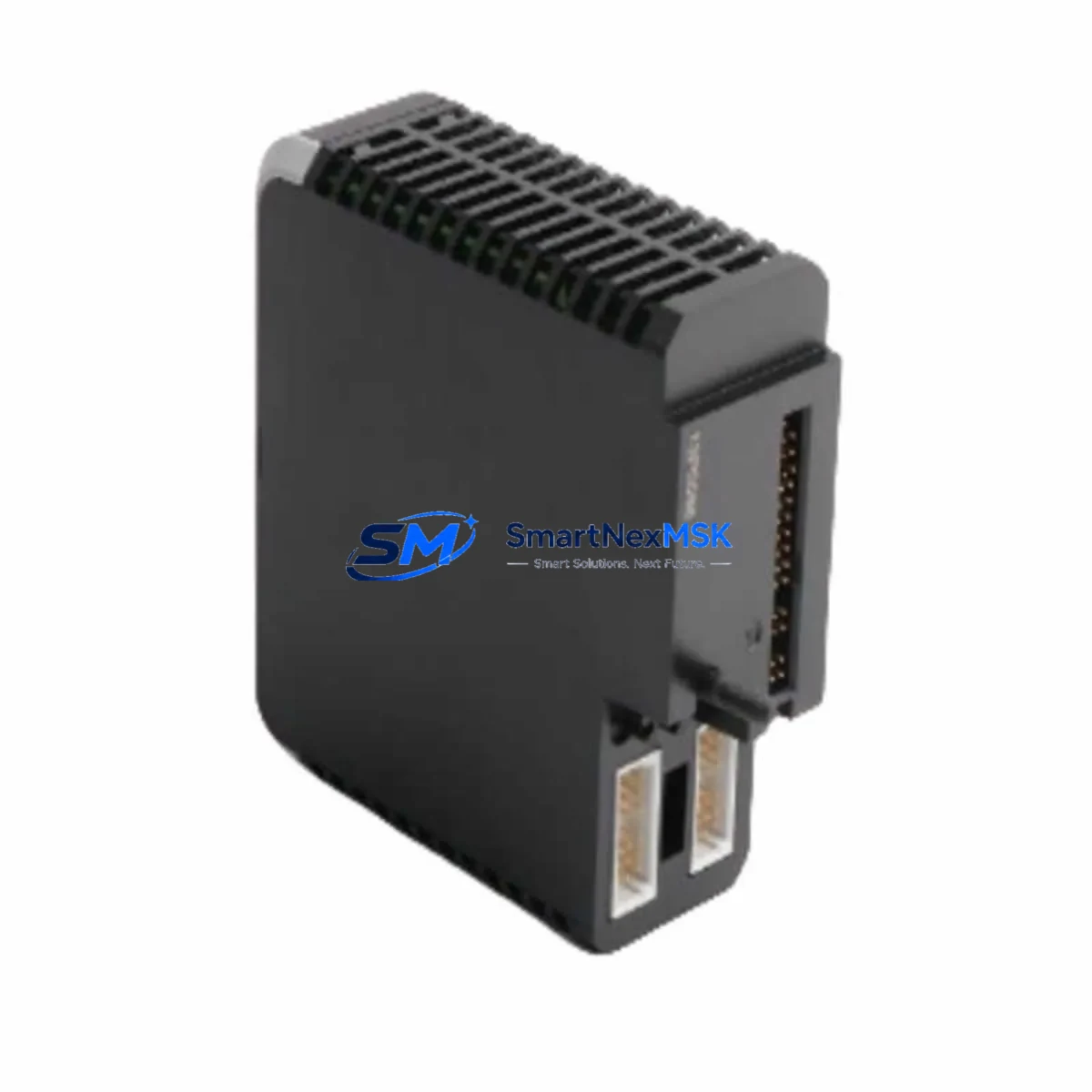
EPRO PR6426/010-140 CON021/916-240 Maintenance-Ready Spare for PR6426 Automation
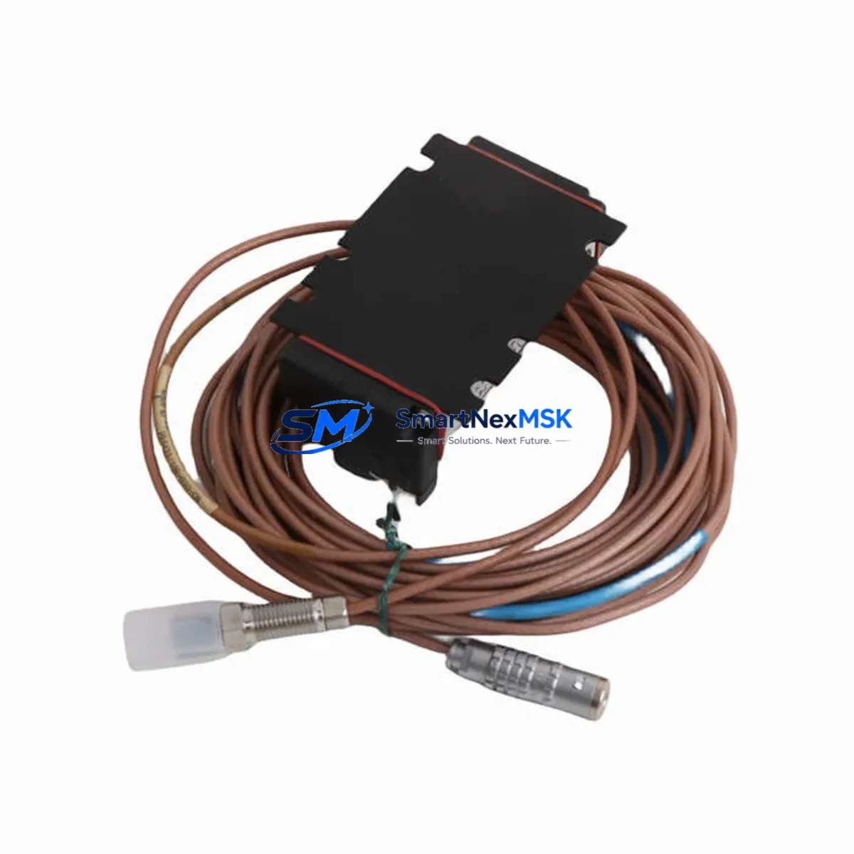
The EPRO PR6426/010-140 + CON021/916-240 eddy current sensor system is a precision proximity measurement assembly widely deployed in turbomachinery protection, rotating equipment monitoring, and critical industrial automation platforms. As OEM production of legacy PR6426 series components enters end-of-life phases, maintaining a verified spare in your MRO inventory is the single most effective strategy for eliminating unplanned downtime in vibration-sensitive processes. This listing provides an original, fully tested EPRO PR6426/010-140 sensor paired with the CON021/916-240 signal conditioning module — ready for immediate site deployment or controlled-environment storage.
Whether you are managing a planned turnaround, responding to a bearing fault alarm, or building a long-term spare parts strategy for aging turbine control cabinets, this assembly delivers the electrical performance and dimensional compatibility required for direct replacement without system reconfiguration.
Spare Maintenance Table
| Parameter | Specification |
|---|---|
| Part Number (Sensor) | PR6426/010-140 |
| Part Number (Conditioner) | CON021/916-240 |
| Brand | EPRO (Baker Hughes / Bently Nevada ecosystem compatible) |
| Series | PR6426 Eddy Current Sensor System |
| Measurement Type | Non-contact eddy current proximity / vibration / position |
| Sensor Cable Length | 1.0 m (extension cable configurable) |
| Output Signal | –24 VDC nominal (standard EPRO eddy current output) |
| Supply Voltage | –24 VDC via CON021 conditioner |
| Operating Temperature | –40 °C to +120 °C (sensor tip); –20 °C to +70 °C (conditioner) |
| Target Material Compatibility | Steel, stainless steel, inconel (standard ferromagnetic/non-ferromagnetic targets) |
| Ingress Protection | IP67 (sensor body) |
| Country of Origin | Germany |
| Application Environment | Turbine bearing housings, compressor pedestals, pump shafts, gearbox monitoring |
| Compatibility | Direct replacement for PR6426/010-140 in existing EPRO / Bently Nevada 3300 series monitor racks |
| Maintenance Recommendation | Replace sensor and conditioner as a matched pair; verify gap voltage and sensitivity after installation |
| Warranty | 12 Months — covers manufacturing defects and electrical performance |
| Pre-shipment Testing | Full electrical output verification and continuity check performed before dispatch |
Maintenance Planning for Continuous Operation
A structured maintenance plan for any rotating equipment installation using the PR6426/010-140 must account for the full signal chain — not just the sensor itself. When a proximity sensor fault is detected or a vibration channel drops offline, experienced maintenance engineers know that the root cause is rarely isolated to a single component. A systematic inspection of the following associated components is strongly recommended during any PR6426 replacement event:
Signal Conditioning and Power Supply: The CON021/916-240 conditioner is the direct electrical partner to the PR6426 sensor. Always replace or bench-test the conditioner alongside the sensor. Upstream, verify the –24 VDC power supply module feeding the conditioner rail — a marginal supply voltage will cause erratic gap readings even with a new sensor installed. If your cabinet uses a dedicated sensor power distribution board, inspect terminal blocks and fuse holders for corrosion or loose connections.
Extension Cables and Connectors: The PR6426 series uses matched extension cables (typically PR6426 extension cable assemblies in 5 m, 9 m, or custom lengths) between the sensor and conditioner. Cable shield integrity is critical — any breach in the coaxial shielding introduces noise that mimics real vibration events. Inspect cable routing for mechanical abrasion at conduit entry points and verify connector torque at both ends.
Monitor Rack I/O Modules: The conditioner output feeds into a vibration monitor rack — commonly a Bently Nevada 3300 series I/O module or equivalent EPRO monitor card. Check the input impedance and channel configuration on the monitor card. A failed input channel on the rack can mask a healthy sensor replacement, leading to unnecessary repeat maintenance cycles.
Relay and Trip Output Modules: Vibration protection systems rely on relay output modules to trigger alarms and machine trips. After replacing the PR6426 assembly, verify that the associated relay module responds correctly to a simulated over-vibration condition. Relay contacts should be inspected for pitting or welding, particularly in high-cycle alarm environments.
HMI and DCS Signal Path: Confirm that the analog signal from the conditioner is correctly received at the DCS analog input card or HMI trend display. A 4–20 mA or voltage signal discrepancy at the DCS end — even with a correctly installed sensor — often points to a wiring fault at the marshalling cabinet terminal strip or a failed signal isolator / signal conditioner barrier in the loop.
Earthing and Shielding: Eddy current systems are highly sensitive to ground loops. After installation, verify that the sensor body earth, cable shield drain wire, and conditioner chassis ground are all connected to a single clean earth point. Floating shields or multiple earth connections are a common source of 50/60 Hz interference on vibration channels.
Building a cabinet-level spare kit around the PR6426/010-140 + CON021/916-240 — including a matched extension cable set, a spare conditioner, and a tested relay output module — reduces mean time to repair (MTTR) from hours to minutes during an unplanned shutdown event.
Site Replacement Workflow
Step 1 — Isolation and Permit: Isolate the vibration monitoring channel at the monitor rack. Do not de-energize the entire rack if other channels are in service. Issue a work permit and confirm the machine is in a safe state for sensor access.
Step 2 — Gap Measurement and Documentation: Before removing the old sensor, record the existing gap voltage from the conditioner output. This baseline value (typically –10 VDC to –18 VDC for standard steel targets) will be your reference for setting the replacement sensor gap. Document the existing cable routing and connector orientation.
Step 3 — Sensor Removal: Disconnect the extension cable at the sensor connector. Unscrew the sensor from its mounting bracket using the correct spanner — avoid gripping the sensor body with pliers. Inspect the mounting threads and bracket for wear or corrosion.
Step 4 — New Sensor Installation: Install the PR6426/010-140 replacement into the mounting bracket. Set the initial gap to the manufacturer-specified nominal distance (typically 1.0 mm for standard configurations). Connect the extension cable and route it following the original path. Secure all cable ties and conduit fittings.
Step 5 — Conditioner Connection and Verification: Connect the extension cable to the CON021/916-240 conditioner. Apply power and measure the output voltage. Adjust the sensor gap until the output matches the documented baseline. Verify the signal at the monitor rack input and confirm the channel reads correctly on the HMI or DCS.
Step 6 — Functional Test and Return to Service: Perform a channel functional test — simulate a vibration event or use a calibrated target displacement to verify alarm and trip setpoints respond correctly. Document the as-left gap voltage and return the channel to normal monitoring service. Update the maintenance record with the new sensor serial number and installation date.
This workflow is applicable to direct replacement of legacy PR6426 series sensors in existing EPRO and Bently Nevada compatible monitor installations, with no firmware changes or rack reconfiguration required.
Spare Parts Support FAQ
Q1: Is this PR6426/010-140 + CON021/916-240 assembly a direct drop-in replacement for my existing installation?
Yes. The PR6426/010-140 sensor and CON021/916-240 conditioner are supplied as a matched pair with the same electrical characteristics as the original OEM assembly. No recalibration of the monitor rack is required, provided the sensor gap is set correctly during installation. Compatibility has been verified for use with standard EPRO and Bently Nevada 3300 series monitor racks.
Q2: What pre-shipment testing is performed on this spare?
Every unit undergoes full electrical output verification prior to dispatch. This includes continuity testing of the sensor coil, output voltage measurement from the CON021 conditioner under nominal supply conditions, and visual inspection of connectors and cable terminations. A test report is available upon request.
Q3: What does the 12-month warranty cover?
The 12-month warranty covers manufacturing defects, electrical performance failures, and component faults that arise under normal operating conditions. It does not cover damage resulting from incorrect installation, mechanical impact, or operation outside the specified environmental limits. Warranty claims are processed with priority to minimize your equipment downtime.
Q4: Can you support long-term or repeat supply of PR6426 series components?
Yes. We maintain dedicated stock of PR6426 series sensors, CON021 conditioners, and associated extension cable assemblies to support planned maintenance schedules, annual turnarounds, and emergency replacement requirements. Contact our team to discuss blanket order arrangements or consignment stock programs for high-criticality installations.
© 2026 SMARTNEXMSK. All rights reserved.
Original Source: https://smartnexmsk.com
Contact: [email protected] | +86 18259474341