EPRO PR9268/201-000 Retrofit-Ready Proximity Transducer for PR9268 Series Control Systems
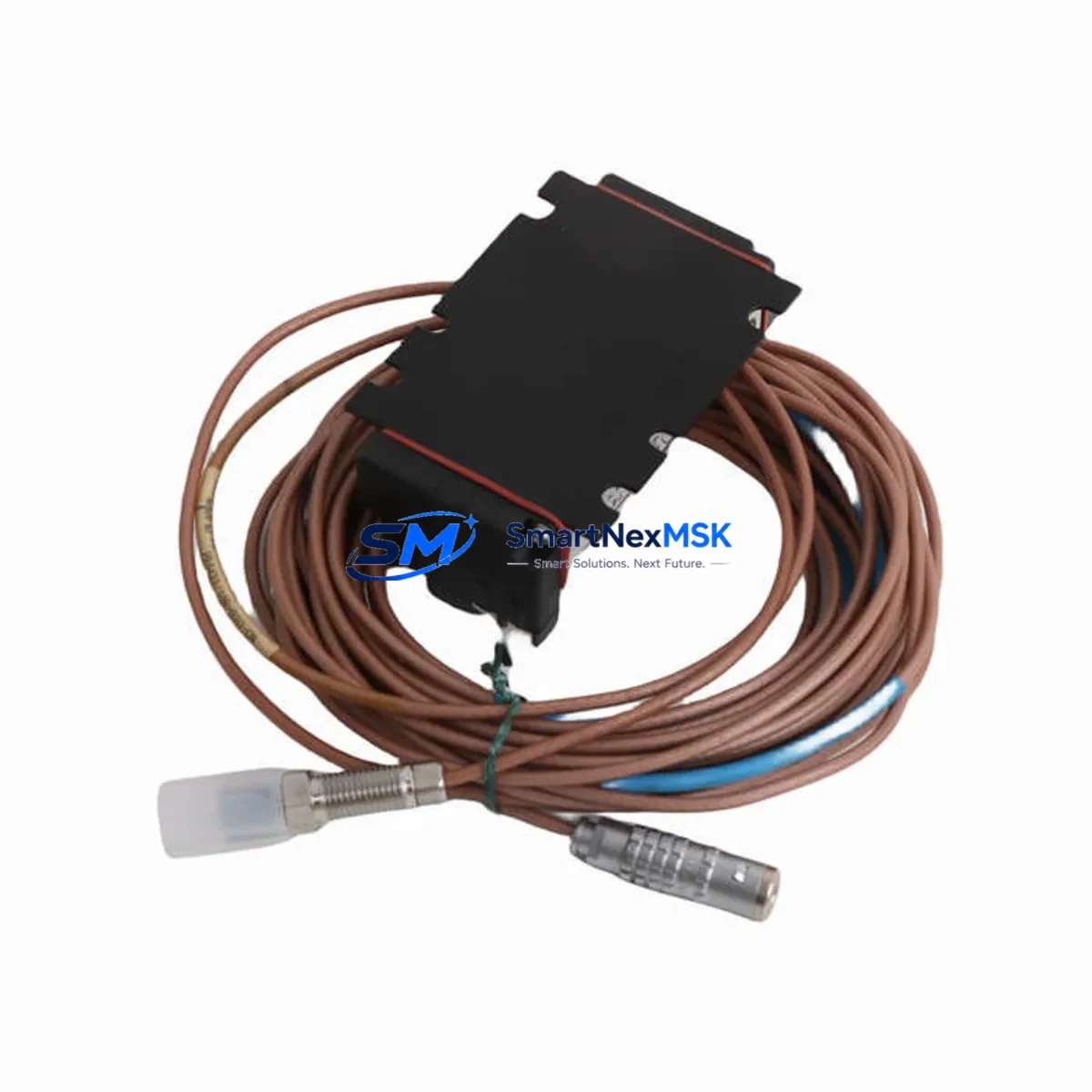
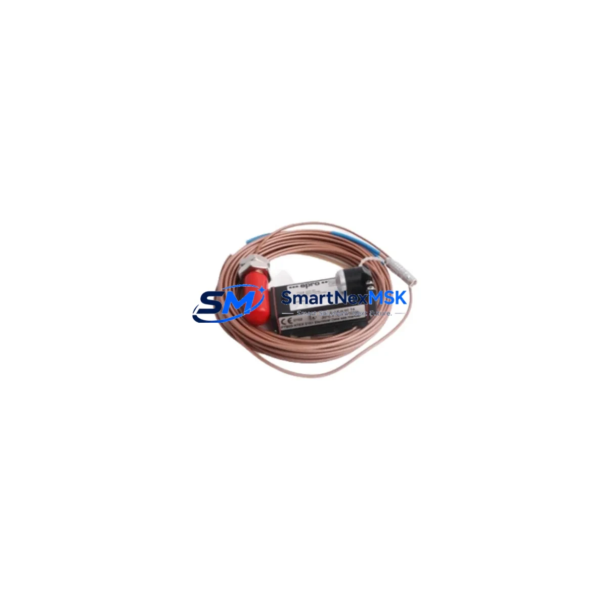
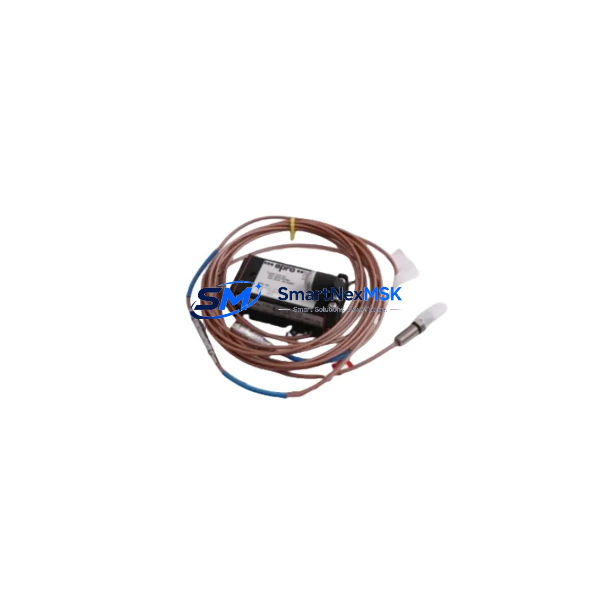
The EPRO PR9268/201-000 is a high-precision eddy current proximity transducer engineered for seamless integration into existing PR9268 Series vibration monitoring and machinery protection systems. Designed with retrofit compatibility as a core specification, this unit serves as a direct replacement for discontinued or end-of-life PR9268 variants, enabling plant engineers to restore full system functionality without redesigning the control architecture. Whether you are upgrading an aging turbine protection panel, recovering from an unplanned component failure, or executing a planned control cabinet modernization, the PR9268/201-000 delivers the dimensional, electrical, and signal-output compatibility required for a smooth, low-risk transition.
Upgrade Compatibility Table
| Parameter | PR9268/201-000 (This Unit) | Retrofit Notes |
|---|---|---|
| Sensing Principle | Eddy Current (Non-contact) | Compatible with all PR9268 Series signal conditioners |
| Cable Length | 5 m (standard) | Verify extension cable length matches original installation; use EPRO CON021 or CON041 extension cables where required |
| Thread / Mounting | M8 × 1 threaded body | Direct fit into existing PR9268 Series mounting brackets; no machining required |
| Output Signal | –24 VDC bias, mV/mil sensitivity | Compatible with PR6423, PR6424, and PR9376 signal conditioners; verify gap voltage at commissioning |
| API 670 Compliance | Yes | Suitable for turbine, compressor, and pump protection per API 670 4th/5th Edition |
| Communication / Protocol | Analog (4–20 mA via conditioner) | No protocol migration required; integrates directly with existing Bently Nevada 3500 Series or EPRO MMS6000 rack systems |
| Installation Requirement | Radial or axial mounting | Confirm target material (steel/alloy) and air gap per calibration chart; re-calibrate after installation |
| Commissioning Focus | Gap voltage, sensitivity, linearity | Use EPRO calibration fixture or portable oscilloscope; document baseline vibration readings post-installation |
| Warranty | 12 Months | Covers manufacturing defects; includes pre-shipment functional test report |
Retrofit Planning for Existing Automation Systems
Successful integration of the PR9268/201-000 into a legacy machinery protection system begins well before the unit arrives on site. Engineers should start by auditing the existing control cabinet layout to confirm available rack slots in the EPRO MMS6000 or compatible Bently Nevada 3500 Series chassis. The signal conditioner — typically a PR9376 or PR6424 — must be verified for firmware revision compatibility, as older conditioner versions may require a parameter reset after transducer substitution.
Terminal wiring is a critical checkpoint. The PR9268/201-000 uses a standard coaxial connector at the transducer body and a terminal block interface at the junction box. Technicians should cross-reference the original wiring diagram against the current cabinet layout, paying particular attention to shield grounding continuity. Improper shield termination is the most common source of noise artifacts in eddy current measurement loops and can trigger false alarms in the machinery protection rack.
Where the original installation used EPRO CON021 extension cables to bridge the distance between the transducer and the signal conditioner, the same cable type should be retained to preserve the calibrated system sensitivity. Mixing cable types within a single measurement chain — for example, substituting a CON041 in a system calibrated with CON021 — will shift the output sensitivity and require full recalibration of the conditioner channel.
For plants running integrated condition monitoring platforms, the PR9268/201-000 feeds directly into the analog input channels of the MMS6000 rack. If the monitoring system also includes a PR9268/010-000 keyphasor transducer for phase-referenced vibration analysis, confirm that the keyphasor channel remains active and correctly phased after the proximity transducer swap. Loss of keyphasor reference will disable 1× and 2× vibration vector displays on the operator HMI, which may be misinterpreted as a system fault rather than a configuration gap.
I/O expansion scenarios — such as adding a new measurement point to an existing rack — should account for the power budget of the signal conditioner backplane. Each active PR9376 conditioner channel draws approximately 35 mA from the rack power supply. Before adding channels, verify that the existing PR9268 Series power supply module has sufficient headroom. If the rack is near capacity, a supplementary power supply module should be installed before the new transducer channel is commissioned.
HMI screen updates are often overlooked during transducer replacements. If the plant uses a SCADA or DCS platform — such as a Siemens S7-300 series controller feeding a WinCC visualization, or an ABB AC500 with connected operator panel — the engineering team should confirm that the tag mapping for the replaced channel remains intact after the conditioner reset. A mismatch between the physical channel address and the HMI tag database will result in a frozen or invalid reading on the operator display, even if the transducer itself is functioning correctly.
Downtime Control During System Migration
Minimizing unplanned downtime is the primary operational constraint in any proximity transducer replacement project. The PR9268/201-000 is stocked for immediate dispatch, with pre-shipment functional testing completed on every unit, reducing the risk of receiving a non-conforming part during a critical maintenance window.
For planned replacements, the recommended approach is a hot-standby swap sequence: install the new PR9268/201-000 in a parallel measurement position, verify gap voltage and sensitivity against the original channel, then transfer the active monitoring function to the new channel before removing the old transducer. This approach keeps the machinery protection system active throughout the swap and avoids the need to bypass the protection rack — a step that carries significant safety and compliance risk in turbine and compressor applications.
Where a parallel installation is not possible due to physical constraints, the replacement should be scheduled during a planned maintenance outage. The original program logic in the signal conditioner and the associated PLC or safety controller — whether a Siemens S7-400H, a Rockwell ControlLogix, or a dedicated machinery protection rack — should be backed up before any hardware is disturbed. Configuration files for the MMS6000 rack, including channel scaling, alarm setpoints, and trip thresholds, must be exported and stored offline prior to the swap.
After installation, the commissioning sequence should follow the EPRO field calibration procedure: set the mechanical gap to the midpoint of the linear range (typically 1.0–1.5 mm for steel targets), measure the DC bias voltage at the conditioner output, and confirm the sensitivity coefficient matches the calibration certificate supplied with the unit. Once the channel is verified, restore all alarm and trip setpoints to their pre-maintenance values and document the as-left gap measurement for the maintenance record.
Communication link continuity — particularly for systems using Modbus RTU or PROFIBUS DP to transmit vibration data to a plant historian or DCS — should be confirmed by observing live data flow at the control room workstation before the maintenance team leaves the field. A brief functional test under low-load machine conditions, if operationally feasible, provides the highest confidence that the replacement has been completed successfully.
Retrofit Support FAQ
Q1: Is the PR9268/201-000 a direct drop-in replacement for other PR9268 Series variants?
The PR9268/201-000 is dimensionally and electrically compatible with other PR9268 Series proximity transducers sharing the same M8 thread, 5 m cable length, and standard coaxial connector. Variants with different cable lengths (e.g., PR9268/202-000 at 9 m) or different connector types require verification against the original installation drawing before substitution. When in doubt, provide the original part number and installation drawing to our technical team for a compatibility confirmation prior to ordering.
Q2: What commissioning steps are required after installation?
After mechanical installation, set the air gap to the midpoint of the transducer’s linear range using a non-ferrous feeler gauge or a calibrated gap-setting tool. Connect the coaxial cable to the signal conditioner (PR9376 or PR6424) and measure the DC output voltage. Confirm the voltage falls within the linear range specified on the calibration certificate. Adjust the gap if necessary, then verify the sensitivity (mV/mil or mV/μm) against the certificate value. Document the as-left gap and output voltage in the maintenance record. No firmware changes are required in the signal conditioner for a like-for-like replacement.
Q3: How is wiring compatibility verified before installation?
Retrieve the original wiring diagram for the measurement loop. Confirm that the coaxial cable shield is grounded at one end only (typically at the signal conditioner terminal block) to prevent ground loops. Verify that the junction box terminals are clean and free of corrosion. If the original installation used EPRO CON021 extension cables, retain the same cable type to preserve system sensitivity. Measure the cable loop resistance before connecting the transducer to confirm there are no open circuits or shorts in the extension cable run.
Q4: What does the 12-month warranty cover, and what testing is performed before shipment?
Every PR9268/201-000 unit undergoes a pre-shipment functional test that verifies DC bias output, sensitivity coefficient, linearity across the measurement range, and connector integrity. The 12-month warranty covers manufacturing defects in materials and workmanship from the date of shipment. It does not cover damage resulting from incorrect installation, mechanical impact, or operation outside the specified environmental limits. A test report is included with each shipment. For warranty claims, contact our technical support team with the unit serial number and a description of the observed fault.
© 2026 SMARTNEXMSK. All rights reserved.
Original Source: https://smartnexmsk.com
Contact: [email protected] | +86 18259474341