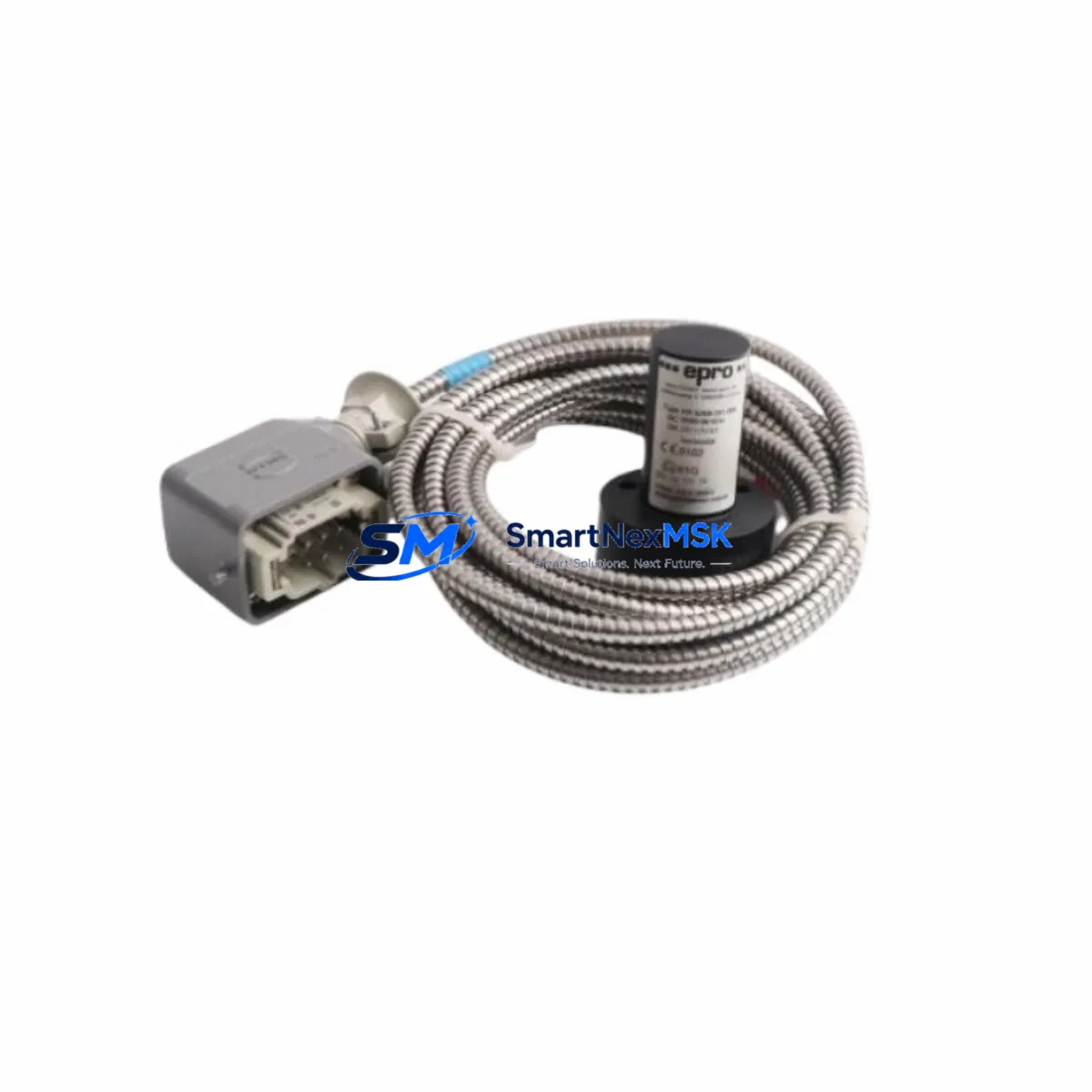
EPRO PR9268/301-000 Retrofit-Ready Eddy Current Proximity Sensor for PR9268 Series Control Systems
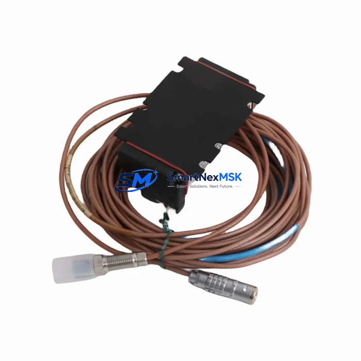
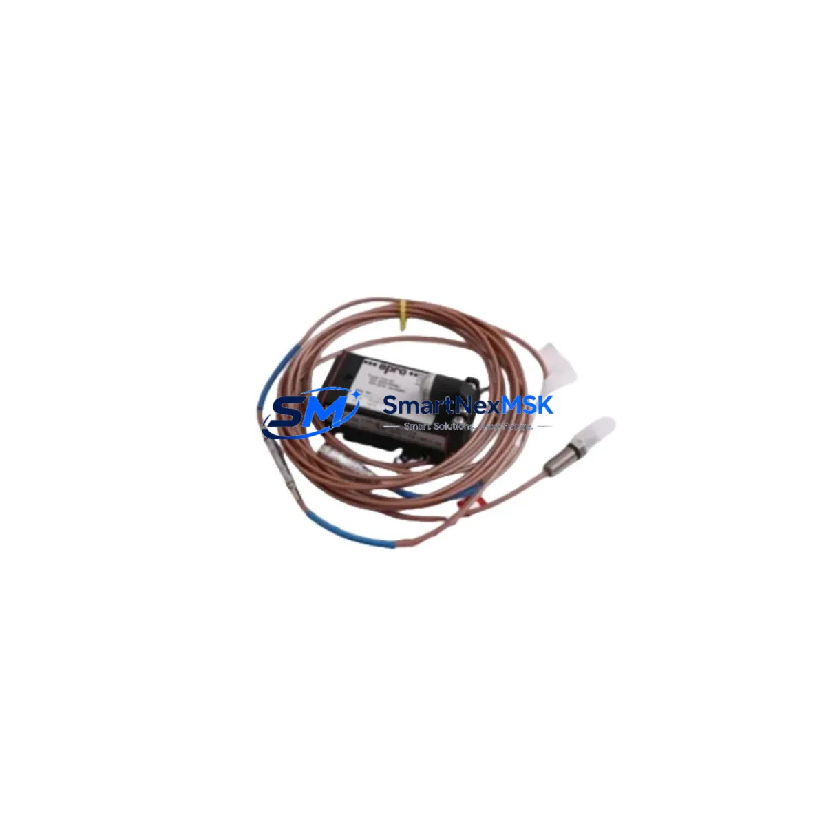
The EPRO PR9268/301-000 is a precision eddy current proximity sensor engineered for seamless integration into existing PR9268 Series vibration monitoring and machinery protection systems. As legacy installations age and OEM support windows close, the PR9268/301-000 provides a verified, drop-in retrofit solution that preserves signal chain integrity, eliminates costly system-wide overhauls, and restores full measurement confidence without interrupting production continuity.
Designed to interface directly with EPRO PR6423 series extension cables and the PR9376 signal conditioning modules, the PR9268/301-000 maintains the same 5 mm nominal sensing range, -24 VDC bias voltage output, and 200 mV/mil sensitivity characteristic that plant engineers rely on in rotating machinery applications including turbines, compressors, pumps, and gearboxes. Its stainless-steel housing and IP67-rated construction ensure reliable performance in high-vibration, high-temperature, and chemically aggressive environments typical of petrochemical, power generation, and heavy manufacturing facilities.
When replacing a failed or end-of-life PR9268/301-000 in an existing rack-mounted protection system, engineers must verify the following before installation: confirm the driver module — typically a PR9376/010-010 or PR9376/010-020 — is calibrated to the correct gap voltage range; inspect the PR6423 extension cable for continuity and shield integrity; validate the terminal block wiring against the original loop drawing; and confirm the vibration monitor input card, such as those found in the EPRO MMS 6000 or MMS 3000 series, is configured for the correct transducer type and full-scale range. Failure to verify these parameters before energizing the loop can result in false trip signals or masked machinery faults.
Upgrade Compatibility Table
| Parameter | PR9268/301-000 (This Unit) | Notes / Retrofit Guidance |
|---|---|---|
| Sensing Range | 5 mm nominal | Verify gap setting matches original calibration record |
| Output Sensitivity | 200 mV/mil (7.87 V/mm) | Must match driver module scale factor setting |
| Bias Voltage | -24 VDC (nominal) | Check driver output before connecting sensor |
| Cable Interface | PR6423 Series Extension Cable | Inspect cable shield continuity; replace if degraded |
| Driver Compatibility | PR9376/010-010, PR9376/010-020 | Recalibrate driver after sensor replacement |
| Monitor Compatibility | MMS 6000, MMS 3000 Series | Confirm input card transducer type configuration |
| Connector Type | Integral coaxial, 1 m armored cable | Match connector type to existing junction box |
| Installation Standard | API 670 compliant | Verify mounting bracket and probe holder dimensions |
| Communication Protocol | Analog (4–20 mA / voltage) | No protocol migration required for direct replacement |
| Warranty | 12 Months | Covered from date of shipment; includes bench test report |
Retrofit Planning for Existing Automation Systems
A successful PR9268/301-000 retrofit begins well before the maintenance window opens. Start by pulling the original loop drawing and confirming the probe-driver-monitor chain. In most PR9268 Series installations, the sensor connects via a PR6423/010-000 or PR6423/010-010 extension cable to a PR9376 driver mounted in the field junction box or directly on the monitor rack. The driver output feeds into an MMS 6000 series vibration monitor input card, which processes the signal and generates trip or alarm outputs to the plant DCS or safety PLC.
Before removing the old sensor, document the installed gap voltage — typically between -10 VDC and -18 VDC at the operating air gap — using a calibrated digital multimeter at the driver output terminals. Record this value; it becomes the baseline for post-installation verification. Loosen the probe locknut, back the sensor out carefully to avoid thread damage on the probe holder, and cap the extension cable connector immediately to prevent contamination.
Install the new PR9268/301-000 by threading it into the probe holder to the documented gap depth, then fine-adjust until the driver output matches the recorded baseline voltage within ±0.5 VDC. Tighten the locknut to the specified torque — typically 20–25 Nm for standard stainless probe holders. Reconnect the PR6423 extension cable, verify shield grounding at one end only to prevent ground loops, and restore power to the PR9376 driver module.
For sites migrating from older PR9268/200-000 or PR9268/100-000 variants, note that the /301-000 suffix designates a 1-meter integral cable with armored jacket — confirm this matches the existing junction box entry point. If the original installation used a bare-end cable terminated at a field terminal strip, a PR6423 adapter pigtail may be required. In multi-channel racks housing both radial vibration and axial position channels, replace sensors channel by channel rather than all at once to maintain partial system protection during the maintenance window.
Sites running Bently Nevada 3500 series monitors alongside EPRO MMS equipment should note that while the PR9268/301-000 is not a Bently Nevada 330100 or 330130 series probe, the output characteristics are compatible with most third-party monitor input cards configured for 200 mV/mil sensitivity — always verify with the monitor manufacturer before cross-brand substitution.
Downtime Control During System Migration
Minimizing unplanned downtime during a PR9268/301-000 replacement requires a structured pre-outage checklist and a clear bypass protocol agreed upon with the control room operator. Before breaking the sensor loop, confirm with the DCS operator that the affected vibration channel can be placed in bypass mode — most MMS 6000 series monitors support per-channel bypass via the front-panel keypad or the MMS Configuration Tool software without requiring a full rack shutdown.
With the channel in bypass, the remaining channels in the rack continue to provide machinery protection, and the plant can maintain production at reduced monitoring confidence rather than a full trip-and-shutdown scenario. Document the bypass start time in the maintenance log and set a hard deadline — typically 2 hours for a single-sensor swap — after which the bypass must be removed regardless of completion status.
After installing the new PR9268/301-000 and verifying the gap voltage, perform a functional check by gently tapping the shaft or using a calibration target to confirm the monitor displays a live, noise-free vibration signal before removing the bypass. If the site uses a System 1 or equivalent condition monitoring platform connected to the MMS rack via Modbus or Ethernet, verify that the historian is receiving valid data on the replaced channel before closing the work order. Retain the original PR9268/301-000 as a failed-unit sample for root-cause analysis and warranty claim processing if applicable.
Retrofit Support FAQ
Q1: Is the PR9268/301-000 a direct drop-in replacement for the PR9268/200-000?
A: The /301-000 and /200-000 share the same sensing element and output characteristics but differ in cable length and jacket construction. The /301-000 features a 1-meter armored integral cable versus the /200-000’s 0.5-meter standard cable. Verify the cable reach to the junction box before ordering; if the original installation used a /200-000 with a PR6423 extension cable, the /301-000 can substitute directly with no extension cable change required.
Q2: Does the PR9268/301-000 require recalibration of the PR9376 driver after installation?
A: Yes. Even though the sensor output characteristics are nominally identical, manufacturing tolerances between individual sensors mean the installed gap voltage will shift slightly. Always perform a gap calibration procedure after installation using the PR9376 calibration port and a calibrated reference gap tool or by adjusting to the documented baseline gap voltage. Record the new calibration values in the site maintenance database.
Q3: What wiring checks are mandatory before energizing the new sensor?
A: Verify continuity of the center conductor and shield of the PR6423 extension cable; confirm shield is grounded at the driver end only; check that the terminal block connections at the driver input match the original loop drawing polarity; and confirm the driver supply voltage is within the specified -24 VDC ±10% range before connecting the sensor. Energizing with reversed polarity or a floating shield can damage the driver input stage.
Q4: What does the 12-month warranty cover, and how is a claim initiated?
A: The 12-month warranty covers manufacturing defects in materials and workmanship from the date of shipment. Each unit ships with a bench test report confirming output sensitivity and bias voltage within specification. To initiate a warranty claim, contact [email protected] with the order number, installation date, failure description, and the bench test report. Units must be returned in original packaging with the failed-unit sample retained for inspection. Shipping costs for warranty returns are covered for confirmed manufacturing defects.
© 2026 SMARTNEXMSK. All rights reserved.
Original Source: https://smartnexmsk.com
Contact: [email protected] | +86 18259474341