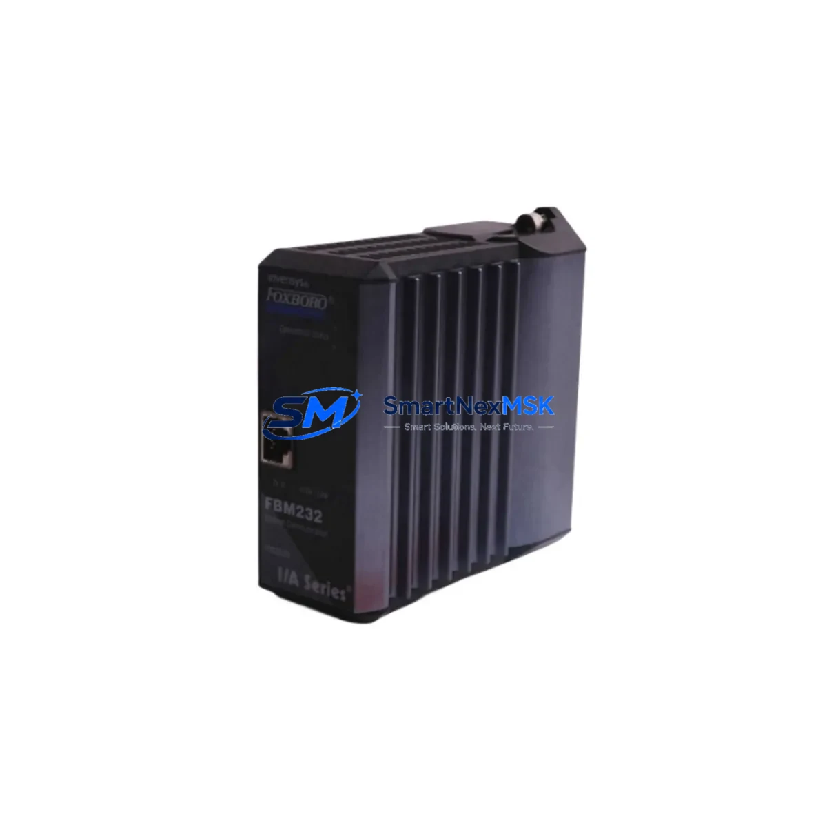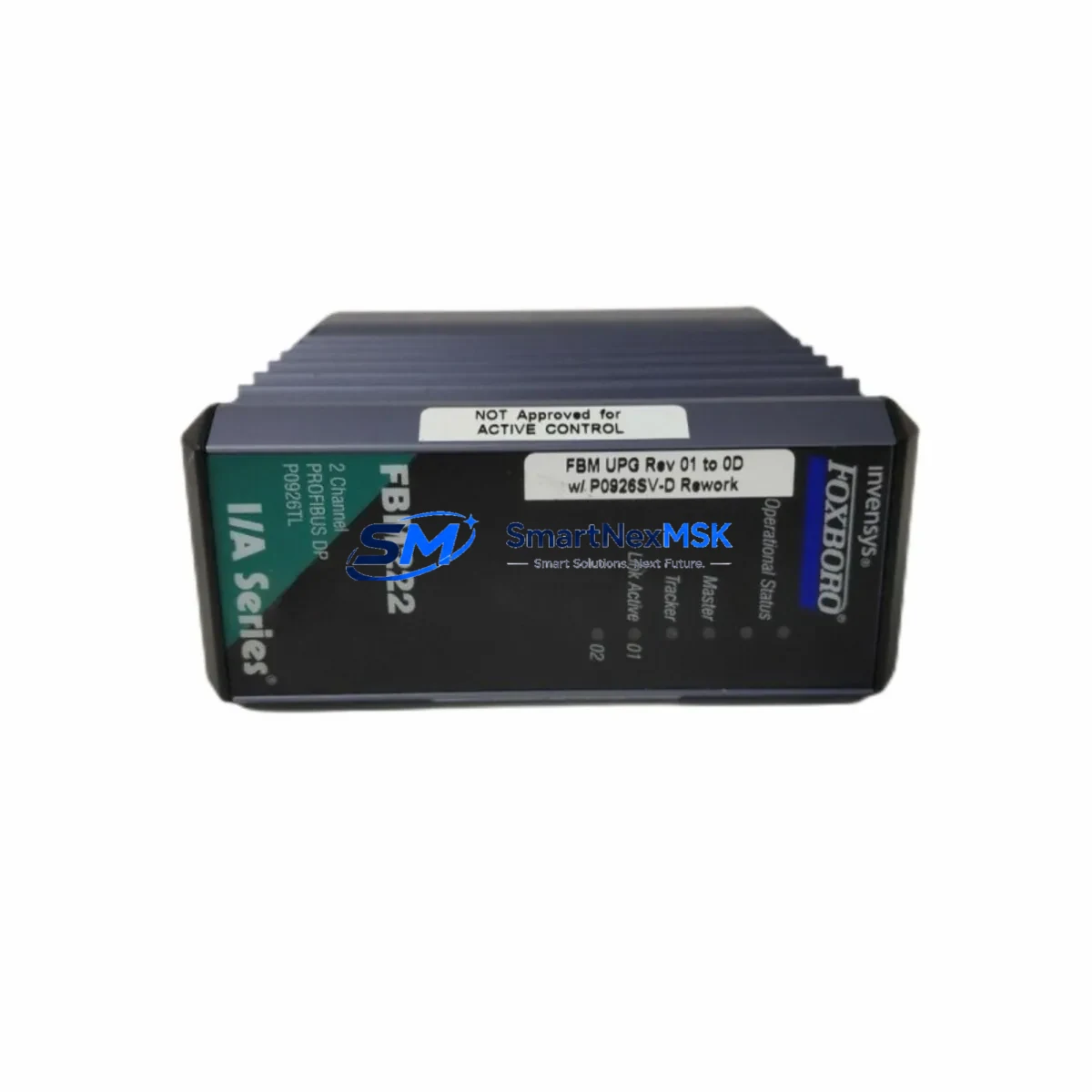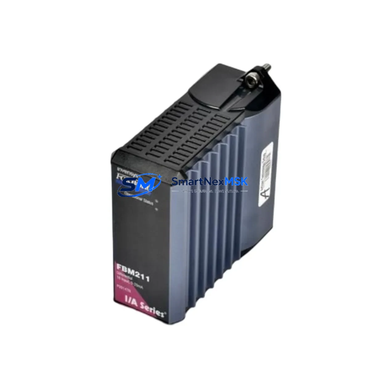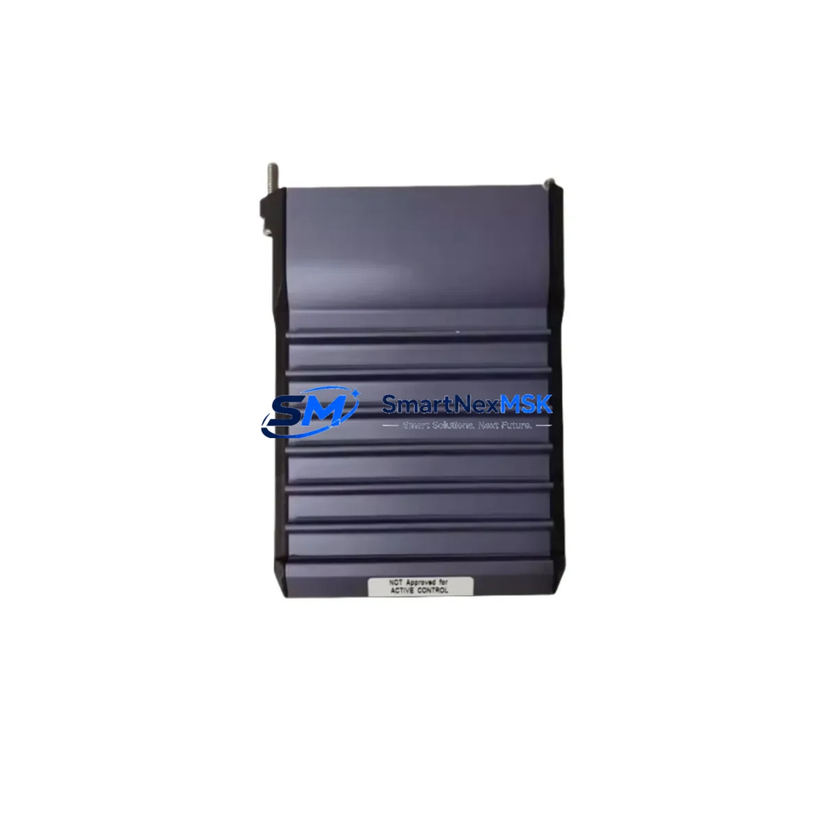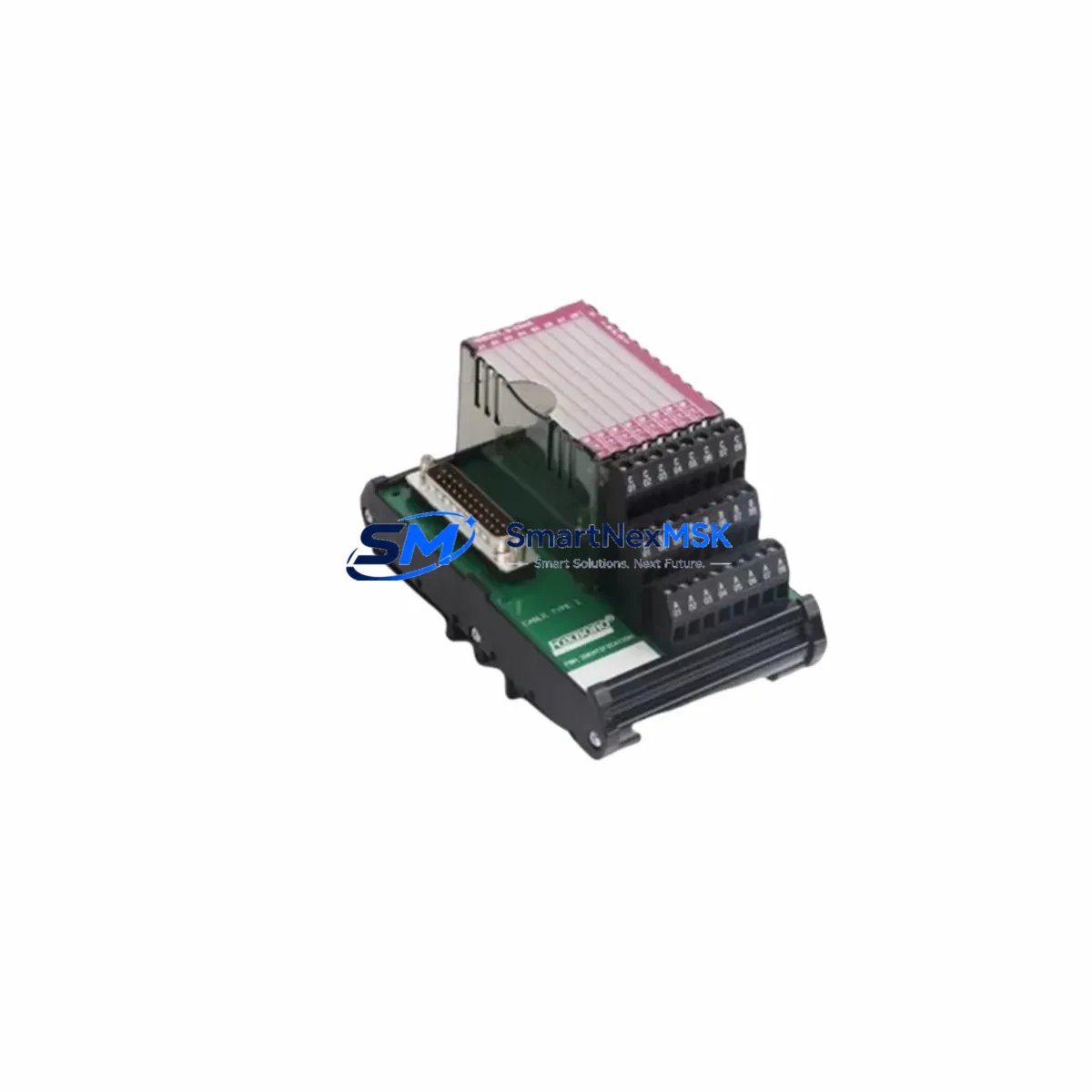
FOXBORO AD916AC FBM202 Maintenance-Ready Spare for I/A Series Automation
The FOXBORO AD916AC FBM202 is a 16-channel Thermocouple and millivolt (mV) Input Field Bus Module designed for the Foxboro I/A Series Distributed Control System (DCS). As a critical signal acquisition component within the I/A Series architecture, the FBM202 handles direct thermocouple and low-level mV signal inputs from field instruments, converting them into digital process values for the DCS controller. When this module fails or degrades, the consequences are immediate: loss of temperature visibility across multiple loops, potential process upsets, and unplanned downtime in continuous manufacturing environments.
Sourced as an original spare, the AD916AC FBM202 offered by SMARTNEXMSK is tested prior to shipment, packaged for safe transport, and backed by a 12-month warranty. Whether you are executing a planned turnaround, responding to an emergency fault, or building a strategic spare parts inventory for aging I/A Series infrastructure, this module is ready for immediate deployment.
Spare Maintenance Table
| Parameter | Specification |
|---|---|
| Part Number | AD916AC |
| Module Type | FBM202 — 16-Channel Thermocouple / mV Input |
| Compatible System | Foxboro I/A Series DCS (Invensys / Schneider Electric) |
| Input Channels | 16 differential thermocouple or mV inputs |
| Thermocouple Types | J, K, T, E, R, S, B (configurable per channel) |
| Signal Range | ±100 mV (mV mode); thermocouple range per type |
| Cold Junction Compensation | Internal, automatic |
| Communication Bus | Fieldbus Module (FBM) — I/A Series Nodebus |
| Power Supply | Supplied via I/A Series baseplate / FBM carrier |
| Operating Temperature | 0°C to 60°C (32°F to 140°F) |
| Humidity | 5% to 95% RH, non-condensing |
| Mounting | FBM Baseplate (standard I/A Series carrier) |
| Isolation | Channel-to-channel and channel-to-bus isolation |
| Diagnostics | On-board self-diagnostics, fault reporting to DCS |
| Origin | USA (Foxboro / Schneider Electric) |
| Condition | Original spare — tested before shipment |
| Warranty | 12 months from date of shipment |
Maintenance Planning for Continuous Operation
The FBM202 sits at the heart of temperature measurement loops in process plants, refineries, chemical facilities, and power generation units. When planning a replacement or conducting a control cabinet inspection, maintenance engineers should treat the AD916AC FBM202 as part of a broader system health review — not an isolated swap.
Begin by verifying the FBM baseplate (carrier assembly) that houses the FBM202. Baseplates accumulate corrosion and connector wear over years of service; a degraded baseplate can cause intermittent faults even after a module replacement. Simultaneously, inspect the Nodebus termination resistors and Nodebus cables connecting the FBM enclosure to the I/A Series Fieldbus Processor (FBP) — signal integrity on the Nodebus directly affects module communication reliability.
On the field wiring side, review the thermocouple extension cables and compensating cables routed to the FBM202 terminal blocks. Degraded insulation, incorrect thermocouple type wiring, or loose terminal connections are common root causes of measurement drift that are often misdiagnosed as module failure. Check the terminal block assemblies for oxidation and confirm that each channel’s thermocouple type matches the software configuration in the I/A Series Integrated Control Configurator (ICC).
For power integrity, verify the I/A Series 24 VDC power supply modules feeding the FBM enclosure. Voltage sag or ripple on the enclosure power rail can cause FBM modules to report spurious faults or fail to initialize after replacement. If the plant uses redundant power feeds, confirm both feeds are healthy before declaring the FBM202 as the sole fault source.
In multi-loop temperature control applications, the FBM202 often works alongside FBM201 (RTD/resistance input modules) and FBM207 or FBM214 analog output modules that drive control valves based on the temperature signals acquired by the FBM202. A fault in the FBM202 will cascade into these output modules if the DCS is configured for tight loop coupling — plan your replacement sequence accordingly to avoid process upsets.
For facilities running aging I/A Series infrastructure, it is also prudent to maintain a spare Fieldbus Processor (FBP) module and at least one spare FBM baseplate alongside the FBM202. These three components form the core of the I/A Series field I/O subsystem, and simultaneous failure of any two will result in extended downtime if spares are not on hand. Additionally, consider stocking signal isolators and surge protection modules for thermocouple inputs in environments with high electrical noise or lightning exposure — these protect the FBM202 from transient damage and extend its service life significantly.
Site Replacement Workflow
Step 1 — Fault Isolation: Confirm the fault is module-level using the I/A Series Station diagnostic display or the DCS alarm summary. FBM202 faults typically appear as “FBM Offline,” “FBM Communication Failure,” or individual channel “Bad PV” alarms. Cross-check with the Nodebus status to rule out upstream communication faults before pulling the module.
Step 2 — Safe Removal: The FBM202 supports hot-swap replacement on most I/A Series configurations. Confirm with your site’s safety procedures whether a hot-swap is permitted or whether a controlled shutdown of the affected FBM enclosure is required. Notify the control room before proceeding.
Step 3 — Module Swap: Slide the faulty AD916AC FBM202 out of the baseplate. Inspect the baseplate connector for damage or contamination. Insert the replacement module firmly until the locking tab engages. The I/A Series DCS will automatically download the module configuration from the Fieldbus Processor — no manual re-configuration is required if the replacement module is the same part number.
Step 4 — Verification: Monitor the DCS station display for FBM202 online status. Confirm all 16 channels return valid PV readings within expected engineering unit ranges. Check for any residual alarms and clear them after verification. Document the replacement in the plant maintenance management system (CMMS) with the module serial number and date.
Step 5 — Faulty Module Disposition: Retain the removed module for failure analysis if required. SMARTNEXMSK can provide exchange or repair evaluation services — contact [email protected] for details.
Spare Parts Support FAQ
Q1: Is the AD916AC FBM202 compatible with all I/A Series DCS versions?
The FBM202 is compatible with the Foxboro I/A Series across multiple generations, including systems running I/A Series software versions 6.x through 8.x. Compatibility with specific Fieldbus Processor (FBP) versions should be confirmed against your site’s I/A Series hardware compatibility matrix. Contact our technical team with your FBP part number for confirmation before ordering.
Q2: What pre-shipment testing is performed on the FBM202?
Each AD916AC FBM202 unit is powered up and functionally tested prior to shipment. Testing includes verification of all 16 input channels, communication bus initialization, and self-diagnostic pass confirmation. A test report is available upon request. Units are shipped in anti-static packaging with protective end caps.
Q3: How should the FBM202 be stored as a long-term spare?
Store the module in its original anti-static bag inside a dry, temperature-controlled environment (10°C to 40°C, <70% RH). Avoid storage near strong magnetic fields or high-vibration areas. Inspect the module annually for connector oxidation. For long-term storage exceeding 24 months, re-test the module before deployment to confirm functionality.
Q4: What is covered under the 12-month warranty?
The 12-month warranty covers manufacturing defects and functional failures under normal operating conditions. It does not cover damage caused by incorrect installation, overvoltage, physical impact, or use outside the module’s rated environmental specifications. Warranty claims are processed within 5 business days of receipt of the returned unit. Replacement or repair is provided at no charge for valid warranty claims.
© 2026 SMARTNEXMSK. All rights reserved.
Original Source: https://smartnexmsk.com
Contact: [email protected] | +86 18259474341