Foxboro P0922YU-FPS400-24 Maintenance-Ready Spare I/A Series Automation
The Foxboro P0922YU-FPS400-24 is a 400W, 24VDC DIN Rail-mount power supply engineered for continuous-duty service within the Foxboro I/A Series Distributed Control System (DCS). As a maintenance-ready original spare, it is the first-line replacement for aging or failed power modules in control cabinets where unplanned downtime carries significant operational and financial risk. Maintenance engineers and procurement teams managing long-lifecycle DCS installations rely on verified original spares like the P0922YU-FPS400-24 to restore system integrity quickly, avoid compatibility issues, and maintain regulatory compliance without re-engineering the power distribution architecture.
Whether you are executing a planned annual shutdown, responding to an emergency power fault, or building a proactive spare-parts inventory for a refinery, chemical plant, or pulp-and-paper facility, the P0922YU-FPS400-24 delivers the electrical performance and form-factor match required for a drop-in replacement. Every unit is inspected, function-tested, and shipped with a 12-month warranty, giving procurement engineers the confidence to stock this module as a critical-path spare.
Spare Maintenance Table
| Parameter | Specification |
|---|---|
| Part Number / SKU | P0922YU-FPS400-24 |
| Brand | Foxboro (Schneider Electric) |
| Series | I/A Series DCS |
| Output Voltage | 24 VDC |
| Output Power | 400 W |
| Mounting Style | DIN Rail |
| Input Voltage | 85–264 VAC, 47–63 Hz (universal input) |
| Cooling Method | Convection / forced air (cabinet-dependent) |
| Operating Temperature | 0 °C to +55 °C |
| Protection Class | IP20 (panel-mount, enclosed cabinet) |
| Compatibility | Foxboro I/A Series FCP270, FCM100, FBM modules; CP60, CP30 controllers |
| Application Environment | Process automation, refinery, chemical, power generation, pulp & paper |
| Replacement Scope | Direct drop-in for P0922YU-FPS400-24; cross-compatible with legacy FPS series power modules |
| Maintenance Interval | Inspect every 12–24 months; replace at first sign of output ripple or thermal alarm |
| Origin | USA |
| Warranty | 12 Months — function-tested before shipment |
Maintenance Planning for Continuous Operation
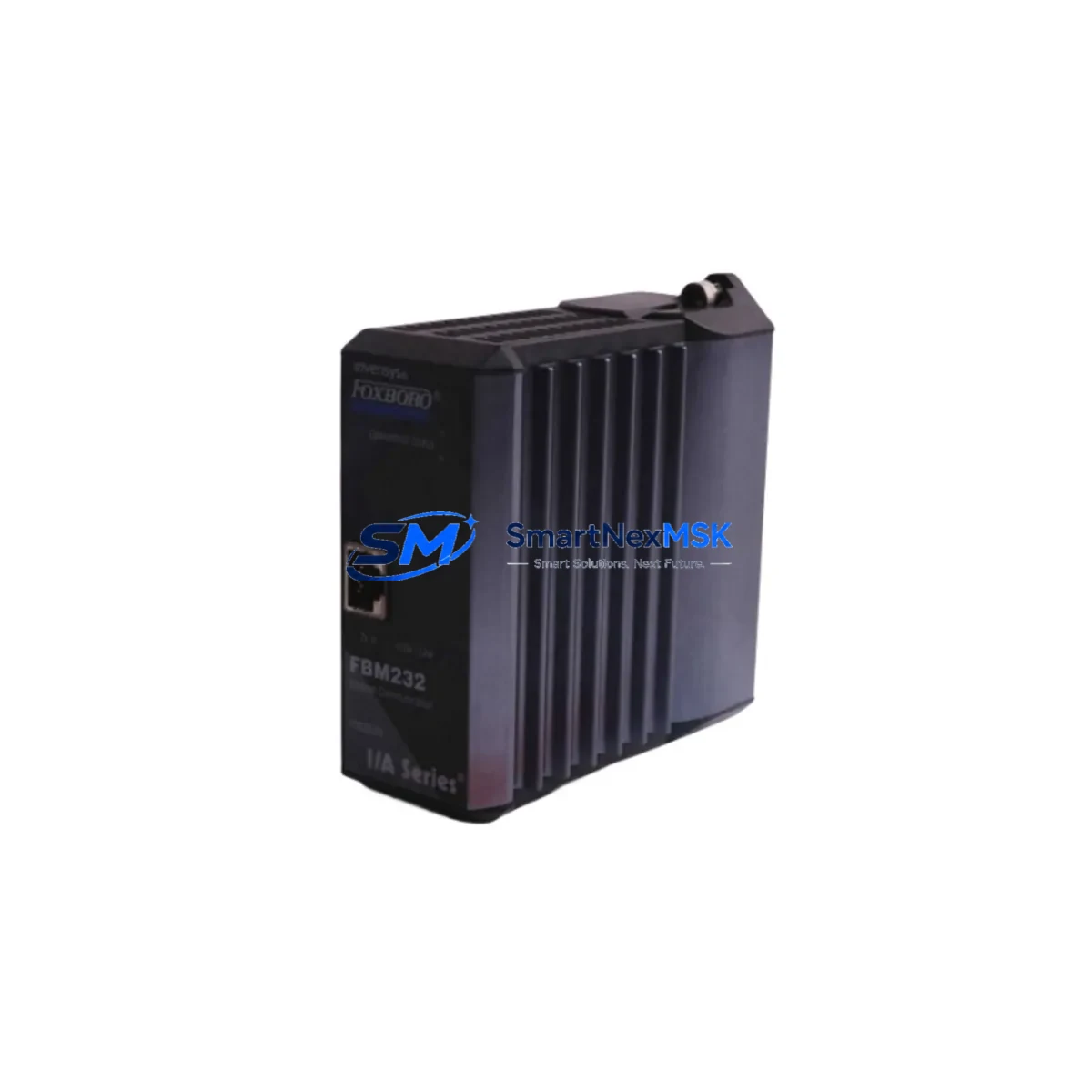
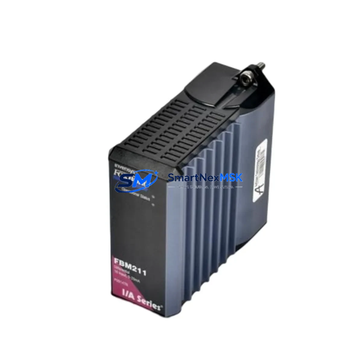
When a P0922YU-FPS400-24 power supply fails or is flagged during a routine control-cabinet inspection, the fault rarely exists in isolation. Experienced maintenance engineers treat a power module replacement as a trigger for a broader cabinet health audit. The 24VDC bus fed by this unit typically powers a cluster of field bus modules (FBMs), including analog input/output FBMs such as the FBM201 and FBM202, digital I/O modules, and HART-enabled signal conditioners. Any sustained undervoltage or ripple event on the 24VDC rail can corrupt configuration memory in these modules or cause spurious I/O state changes — so verifying bus voltage stability after installing the replacement supply is a mandatory first step.
Beyond the I/O layer, the power supply feeds the backplane of the FCP270 Field Control Processor and associated FCM100 Fieldbus Communication Modules. These processors manage real-time control execution and FOUNDATION Fieldbus or PROFIBUS segment communication; a marginal power supply that passes initial inspection but degrades under load can cause intermittent controller resets that are difficult to diagnose without a power-quality logger. Replacing the P0922YU-FPS400-24 proactively — rather than reactively — eliminates this failure mode entirely.
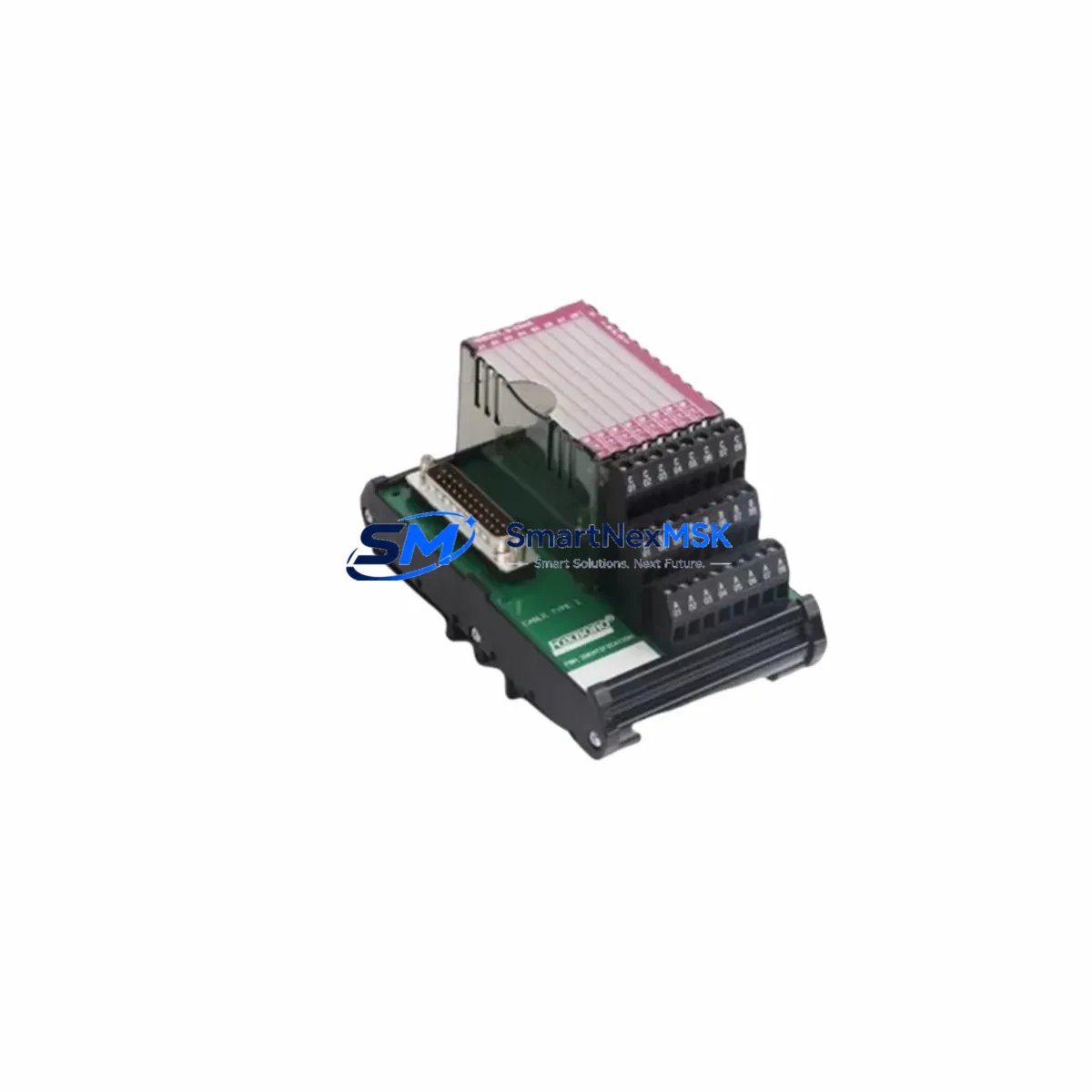
During the same maintenance window, technicians should inspect the terminal blocks and wiring harnesses on the 24VDC distribution bus, check the condition of DIN rail-mount fuse holders (typically 4A–10A blade or cylindrical fuses protecting individual module branches), and verify that surge protection devices (SPDs) on the AC input side have not sacrificed themselves during a prior transient event. If the cabinet includes a redundant power supply module (a second FPS400-24 in a 1+1 configuration), its output diode and load-sharing circuitry should be tested simultaneously. Neglecting the redundant unit during a single-unit replacement is a common oversight that leaves the system with false redundancy.
For sites running Foxboro’s FoxView or IA Series Workstation HMI, confirm that the HMI communication path through the Nodebus or Mesh Control Network (MCN) remains stable after power restoration. Communication modules such as the NB-FBM or dedicated Ethernet gateway cards are sensitive to power sequencing; a hard power cycle of the supply can occasionally require a module re-initialization. Keeping a spare CP60 Controller Personality Module and a pre-configured FCM100 in the site spare-parts kit alongside the P0922YU-FPS400-24 ensures that a single cabinet fault can be fully resolved within one maintenance shift rather than requiring a parts-expedite delay.
Site Replacement Workflow
Step 1 — Isolation and safety: Isolate the AC input feed to the power supply using the dedicated MCB or isolation switch. Confirm zero energy with a calibrated multimeter on both the AC input terminals and the 24VDC output bus before touching any wiring.
Step 2 — Document current configuration: Photograph terminal wiring, record the output voltage trim setting (if adjusted from factory default), and note any alarm relay wiring on the OK/FAULT contacts. The P0922YU-FPS400-24 includes a dry-contact fault relay that is often wired into the plant DCS alarm system — this wiring must be replicated exactly on the replacement unit.
Step 3 — Physical swap: Release the DIN rail locking tab, slide the failed unit off the rail, and mount the replacement. Reconnect AC input, 24VDC output bus bars, and the fault relay wiring in the documented sequence. Torque all terminals to the manufacturer’s specification (typically 0.5–0.6 N·m for 2.5mm² conductors).
Step 4 — Power-up and verification: Restore AC input and measure output voltage at the bus bar — target 24.0 VDC ±1%. Observe the OK LED on the supply front panel and confirm the fault relay contact has transferred to the healthy state. Check the FCP270 controller status display for any module fault codes that may have latched during the outage.
Step 5 — System validation: Cycle through all FBM I/O channels in the DCS operator station to confirm correct signal values. Run a 15-minute load soak with the cabinet at normal operating load before returning the loop to automatic control. Log the replacement in the site CMMS with the new unit’s serial number and warranty expiry date.
This workflow is applicable whether you are replacing an identical P0922YU-FPS400-24 or upgrading from an older FPS-series power module. The DIN rail form factor and terminal layout are consistent across the FPS product family, making the swap straightforward for any technician familiar with the I/A Series cabinet architecture.
Spare Parts Support FAQ
Q1: Is the P0922YU-FPS400-24 still in production, and how long can I expect supply availability?
The P0922YU-FPS400-24 is an established spare within the Foxboro I/A Series ecosystem. We maintain stock of both new and refurbished-to-spec units to support long-lifecycle DCS installations. Our sourcing network is specifically structured to support sites that cannot migrate to newer control platforms on a short timeline, and we provide long-term supply commitments for critical-path spares upon request.
Q2: How do I verify compatibility before ordering if my cabinet uses a slightly different FPS module variant?
Provide your existing module’s full part number, cabinet drawing reference, or a photograph of the installed unit’s nameplate. Our technical team will confirm electrical compatibility, terminal layout equivalence, and any firmware or configuration considerations before shipment. We do not ship units that cannot be confirmed compatible for your specific application.
Q3: What pre-shipment testing is performed on each unit?
Every P0922YU-FPS400-24 is bench-tested under a resistive load equivalent to 80% of rated output (320W) for a minimum of 30 minutes. Output voltage, ripple, and fault relay function are verified and recorded. A test certificate is available upon request and accompanies all units shipped under a purchase order that specifies it.
Q4: What does the 12-month warranty cover, and what is the claims process?
The 12-month warranty covers all electrical and mechanical defects under normal operating conditions as defined by the Foxboro I/A Series installation guidelines. If a unit fails within the warranty period, contact us with the serial number and a brief fault description. We will arrange a replacement shipment — typically within 3 business days — and provide a prepaid return label for the failed unit. Warranty claims caused by incorrect installation, overvoltage events, or physical damage are assessed case by case.
© 2026 SMARTNEXMSK. All rights reserved.
Original Source: https://smartnexmsk.com
Contact: [email protected] | +86 18259474341