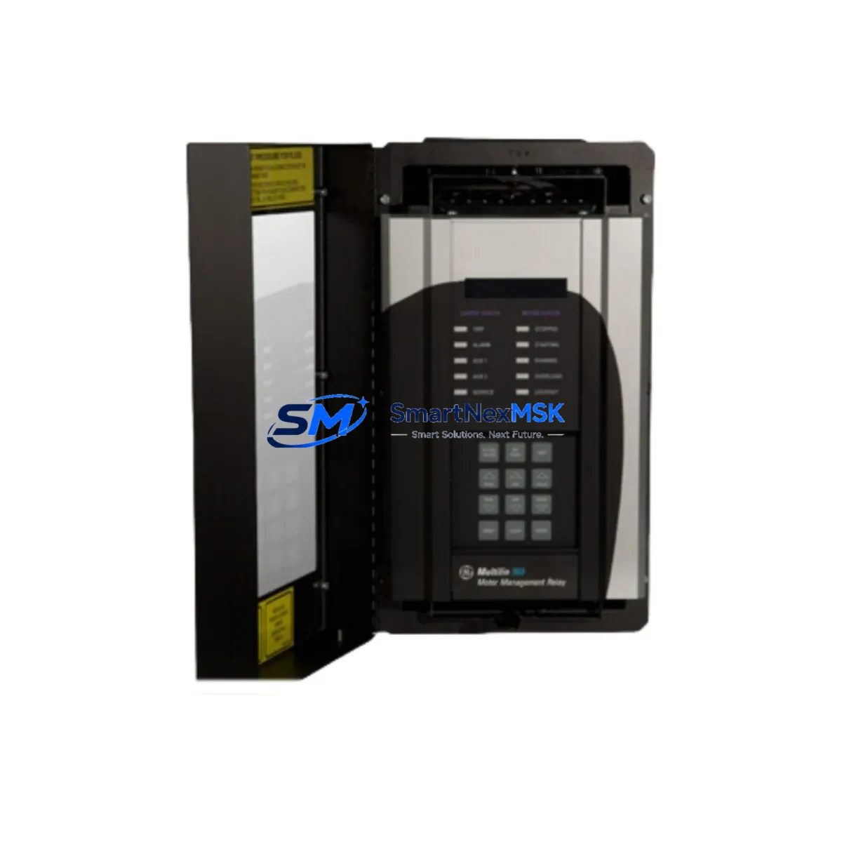
GE 369B1848G5001 Spare for MVP10 Automation: Spare Replacement & Industrial Downtime Risk Control
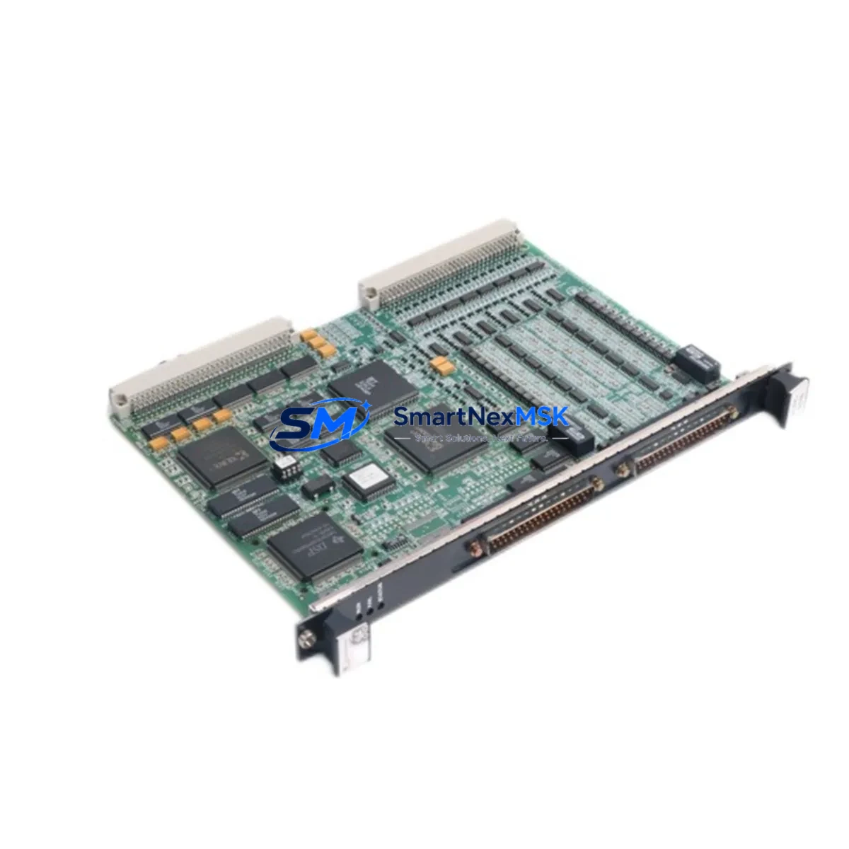
The GE 369B1848G5001 is an original RTD (Resistance Temperature Detector) input module designed for GE’s MVP10 industrial automation platform. In process-critical environments — including power generation, petrochemical, pulp and paper, and heavy manufacturing — this module serves as the primary interface between field-mounted RTD sensors and the control system’s temperature acquisition loop. When this module fails or degrades, the result is loss of temperature feedback, potential process excursions, and unplanned downtime. Maintaining a verified spare on the shelf is the most effective strategy for rapid restoration of normal operations.
At SMARTNEXMSK, every GE 369B1848G5001 unit is sourced from authorized supply channels, inspected against OEM specifications, and tested prior to shipment. Each unit ships with a 12-month warranty covering manufacturing defects and functional performance. Our global logistics network supports urgent dispatch to minimize the gap between fault detection and system restoration.
Spare Maintenance Table
| Parameter | Specification / Detail |
|---|---|
| Part Number | 369B1848G5001 |
| Manufacturer | GE (General Electric) |
| Module Type | RTD Input Module |
| Compatible Platform | GE MVP10 Industrial Automation System |
| Input Type | Resistance Temperature Detector (RTD), 2/3/4-wire configurations |
| Measurement Range | Per OEM specification for Pt100 / Pt1000 RTD sensors |
| Signal Resolution | High-resolution analog temperature acquisition |
| Power Supply | Backplane-powered via MVP10 rack; no external supply required |
| Installation | Direct rack insertion into MVP10 I/O chassis; no tools required |
| Operating Temperature | 0°C to 60°C (standard industrial enclosure environment) |
| Humidity | 5% to 95% RH, non-condensing |
| Compliance | CE, UL (per GE MVP10 platform certification) |
| Country of Origin | United States |
| Condition | Original, new or refurbished-to-spec; tested before shipment |
| Warranty | 12 Months — covers manufacturing defects and functional performance |
| Lead Time | In-stock units ship within 1–3 business days; urgent orders prioritized |
Maintenance Planning for Continuous Operation
When a maintenance or reliability engineer schedules a planned inspection or responds to a temperature-loop fault on an MVP10 system, the 369B1848G5001 RTD input module is rarely the only component that warrants attention. A disciplined spare-parts strategy and thorough site inspection should encompass the full signal chain and supporting infrastructure.
Begin with the RTD field sensors themselves — Pt100 or Pt1000 elements installed in thermowells. Sensor drift, moisture ingress, or broken leads are common root causes of apparent module faults. Verify sensor resistance at the terminal strip before condemning the module. Next, inspect the field wiring and terminal blocks: corroded terminals, loose screws, or damaged cable insulation in the junction box can introduce resistance errors that mimic module failure.
Within the control cabinet, the MVP10 power supply module — which provides regulated backplane voltage to all I/O cards including the 369B1848G5001 — should be checked for output voltage stability and ripple. A degraded power supply can cause intermittent faults across multiple I/O modules simultaneously. Alongside the power supply, inspect the MVP10 I/O backplane and rack chassis for bent connector pins, oxidation on the card-edge contacts, or physical damage from vibration.
If the MVP10 system includes analog output modules driving control valves or variable-speed drives based on temperature setpoints, verify that these modules are receiving correct process values after the RTD module is replaced. Similarly, any signal isolators or signal conditioners installed between the RTD module and downstream control loops should be tested for correct pass-through and isolation integrity.
For systems with GE Mark series communication modules or Profibus/Modbus interface cards sharing the same rack, confirm that the replacement procedure — which involves powering down the rack slot — did not disrupt communication bus timing or cause address conflicts. Review the HMI (Human-Machine Interface) tag configuration to ensure the temperature point is correctly mapped to the new module’s channel address.
Finally, check the fuse holders and circuit protection on the 24 VDC distribution rail feeding the I/O section. A blown fuse upstream of the RTD module can cause a no-signal condition that is easily misdiagnosed as module failure. Maintaining a stock of compatible fuses, terminal block covers, and labeling materials alongside the 369B1848G5001 spare ensures that a complete, professional restoration can be completed in a single maintenance window.
Site Replacement Workflow
Step 1 — Fault Isolation: Confirm the fault is isolated to the 369B1848G5001 module by checking the MVP10 diagnostic display or SCADA alarm log. Note the slot address and channel number of the faulted input.
Step 2 — Safe Isolation: Follow site LOTO (Lockout/Tagout) procedures. For hot-swap capable MVP10 configurations, verify whether the slot supports live removal; if not, de-energize the rack section before extraction.
Step 3 — Module Extraction: Release the module locking lever, slide the 369B1848G5001 out of the rack, and inspect the backplane connector for damage or contamination before inserting the replacement unit.
Step 4 — Replacement Insertion: Insert the new 369B1848G5001 into the same slot. The module is keyed to prevent incorrect installation. Confirm the locking lever engages fully.
Step 5 — Configuration Verification: If the MVP10 system stores module configuration in the rack controller, verify that the replacement module auto-downloads its channel configuration. For systems requiring manual configuration, use the GE programming tool to re-enter RTD type, range, and engineering unit settings.
Step 6 — Functional Test: Apply a known resistance value to the input channel using a decade resistance box or RTD simulator. Confirm the displayed temperature on the HMI matches the expected value within the module’s specified accuracy.
Step 7 — Return to Service: Remove test equipment, reconnect field wiring, clear alarms, and document the replacement in the site maintenance log. Update the spare-parts inventory to trigger reorder of a replacement 369B1848G5001 unit.
This workflow is applicable to both emergency breakdown replacements and planned preventive maintenance cycles, and is designed to minimize total downtime from fault detection to verified restoration.
Spare Parts Support FAQ
Q1: Is the 369B1848G5001 still available as a new original part, or only as refurbished?
SMARTNEXMSK maintains stock of both new original and professionally refurbished-to-specification units. All refurbished units undergo full functional testing against GE OEM performance criteria before shipment. The condition is clearly stated on the order confirmation. Both conditions are covered by the 12-month warranty.
Q2: How do I verify compatibility before ordering if my MVP10 system has been upgraded or modified?
Provide your system’s rack model number, firmware revision, and the existing module’s label information (including any suffix codes on the 369B1848G5001 part number) when contacting our technical team. We will cross-reference against GE’s compatibility matrix and confirm the correct revision for your application before shipment.
Q3: What pre-shipment testing is performed on each unit?
Every 369B1848G5001 unit is powered up and tested for correct RTD input response across the full channel range, backplane communication integrity, and LED status indication. A test report is available upon request. Units that do not pass all test criteria are not shipped.
Q4: What is the recommended inventory strategy for this module in a critical process plant?
For plants operating MVP10 systems in continuous-process or safety-critical applications, we recommend maintaining a minimum of one 369B1848G5001 spare per four installed units, with a maximum replenishment lead time of 30 days. For legacy systems where GE has discontinued active production, holding two or more units is advisable to cover the extended period until a system migration can be planned and budgeted.
© 2026 SMARTNEXMSK. All rights reserved.
Original Source: https://smartnexmsk.com
Contact: [email protected] | +86 18259474341