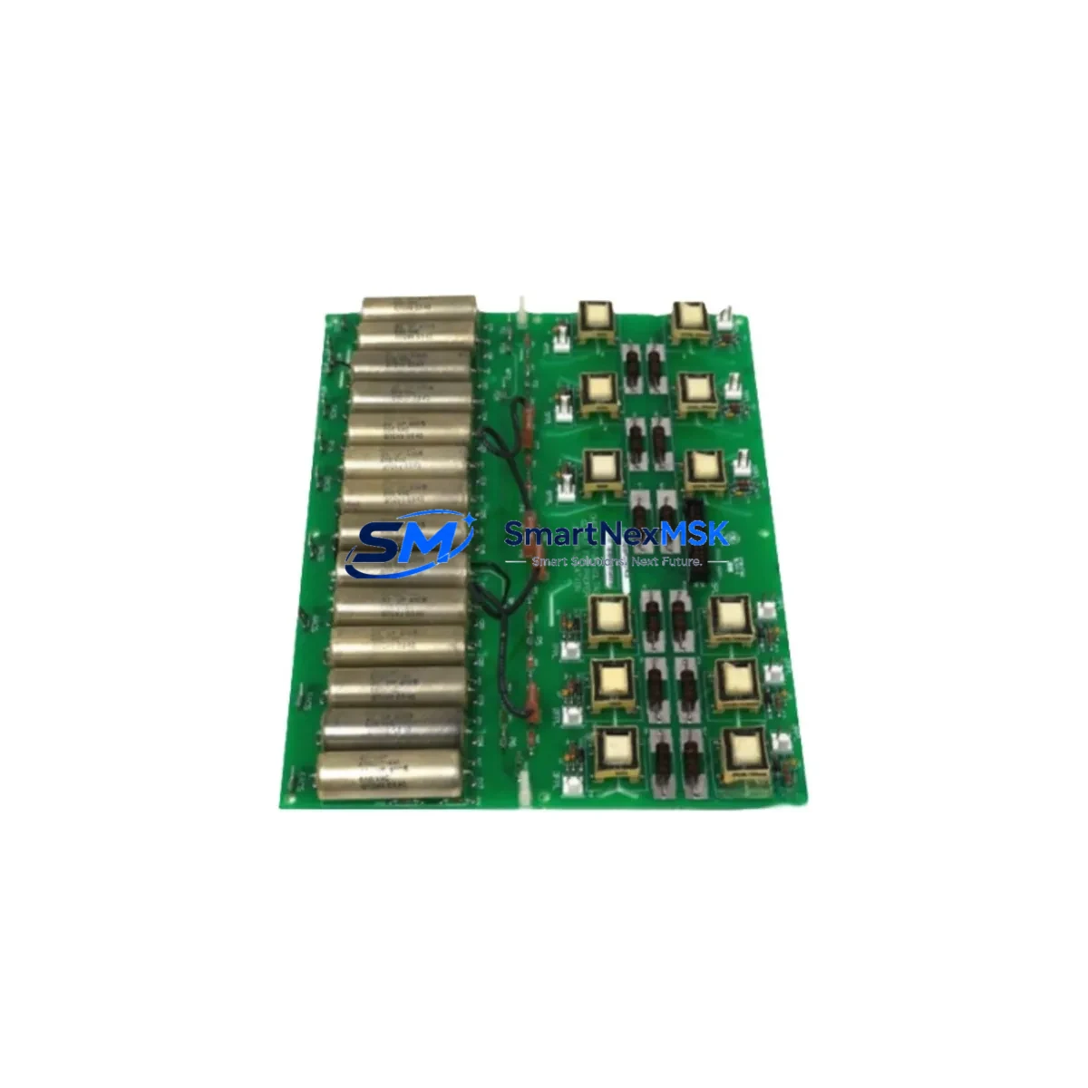
GE DS200PCCAG7ACB Retrofit-Ready Power Connect Board for Mark V Speedtronic Control Systems
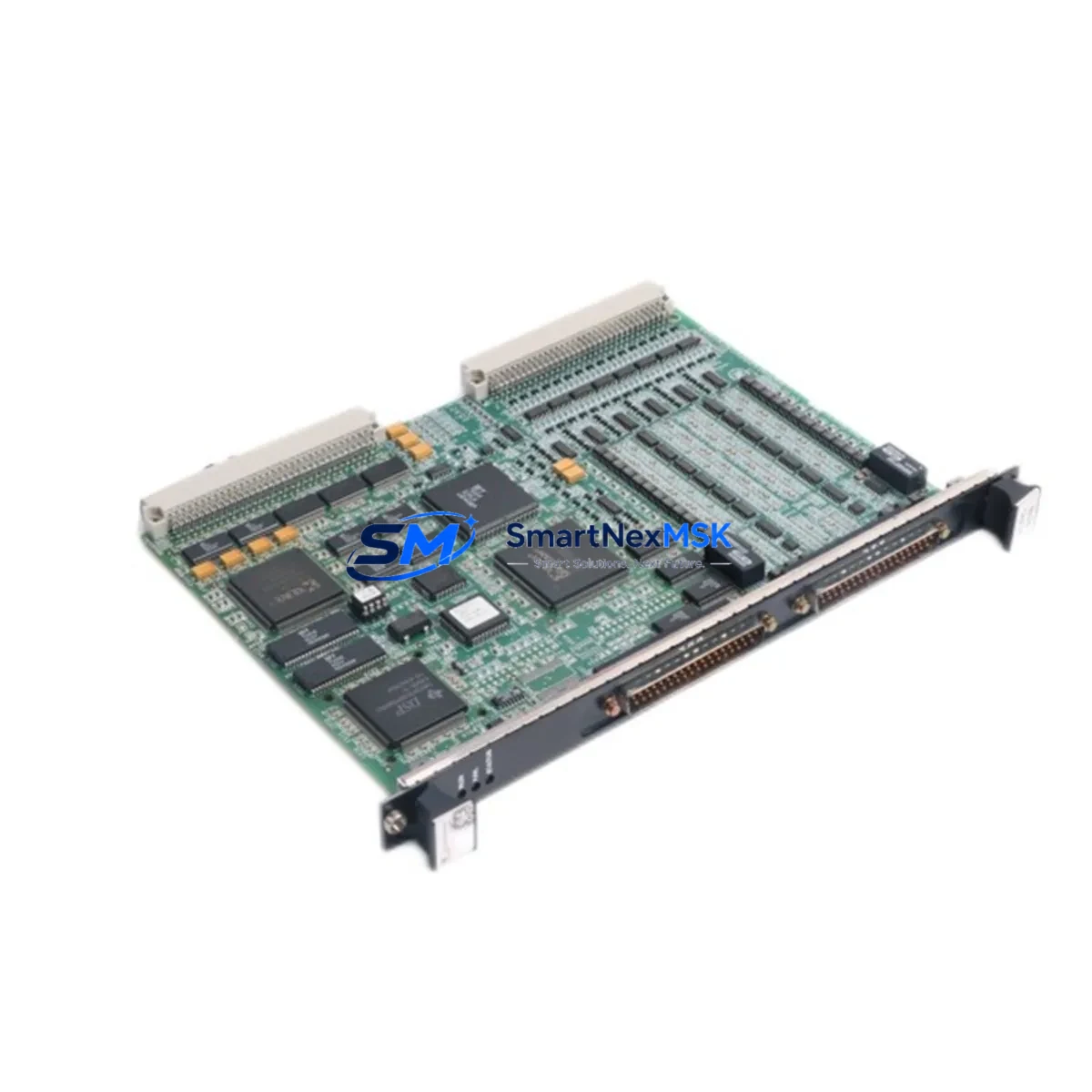
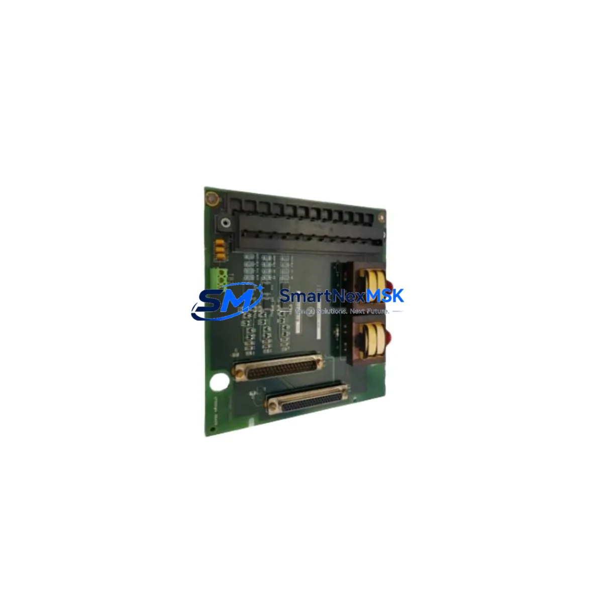
The GE DS200PCCAG7ACB is a Power Connect Board designed for the GE Mark V Speedtronic turbine control platform — one of the most widely deployed gas turbine control systems in power generation, oil & gas, and industrial process facilities worldwide. As the Mark V platform approaches end-of-life and OEM support becomes increasingly limited, the DS200PCCAG7ACB has become a critical retrofit and replacement component for engineers managing aging control infrastructure. Whether you are executing a like-for-like spare parts replacement, a partial panel upgrade, or a full control system modernization, this board provides the electrical interface and power distribution functions required to maintain system continuity.
The DS200PCCAG7ACB interfaces directly with the Mark V rack architecture, distributing regulated DC power to downstream I/O boards including the DS200IOCAG1A I/O controller and the DS200TCQAG1BHF terminal board. During a retrofit, engineers must verify the incoming DC bus voltage levels — typically +5 VDC, ±15 VDC, and +28 VDC rails — against the original power supply module output, such as the DS200VPBLG1AEE power supply board, to ensure compatibility before energizing the replacement unit. Mismatch in rail voltage or connector pinout between board revisions (e.g., G7A vs. G6A suffix variants) can cause downstream faults on the DS200SDCIG2AEB signal conditioning board or trigger protection trips on the DS200TCDAG1AAA diagnostic board.
When planning a retrofit around the DS200PCCAG7ACB, the following pre-installation checks are essential. First, confirm the backplane connector alignment with the existing Mark V rack — the board uses a standard VME-style edge connector, but revision-specific keying must be verified against the rack’s DS200TCEAG1BHF terminal board layout. Second, review the module address configuration: the Mark V system assigns hardware addresses via DIP switch settings on the board itself, and these must match the address map defined in the original CIMPLICITY HMI configuration or the Toolbox ST programming environment. Incorrect addressing will cause the scan to fail silently, which is a common source of post-replacement commissioning delays.
For facilities running legacy communication links — including the Mark V’s proprietary IONet or ARCNET-based control network — the DS200PCCAG7ACB retrofit must be coordinated with any planned migration to Ethernet-based protocols. If the upgrade path includes transitioning to a GE Mark VIe platform, the power distribution architecture changes significantly, and the DS200PCCAG7ACB will need to be replaced by the IS200PCCAG1A or equivalent Mark VIe power connect module. In such cases, the terminal wiring from the existing DS200TBCIH1C terminal board must be re-mapped to the new Mark VIe I/O pack connectors, and the control logic exported from the Mark V Toolbox must be re-validated in the Mark VIe ToolboxST environment before go-live.
For partial upgrades where the Mark V core controller (the , , and processor boards) is retained but peripheral I/O boards are being refreshed, the DS200PCCAG7ACB can be installed as a direct replacement with minimal rewiring. The board’s field wiring terminals are compatible with the existing cable harness in most Mark V panel configurations, reducing installation time to under two hours in a well-documented panel. Engineers should photograph the existing wiring before removal, verify terminal torque specifications (typically 0.5–0.8 Nm for signal terminals), and perform an insulation resistance test on the field cables before reconnecting to the new board.
Downtime management is a primary concern in any turbine control retrofit. The DS200PCCAG7ACB is supplied pre-tested and function-verified against GE Mark V electrical specifications, allowing it to be installed and energized without bench calibration. Our standard outage support package includes pre-shipment functional test reports, wiring diagrams cross-referenced to the original GE Mark V panel drawings, and remote technical support during the commissioning window. All units are covered by a 12-month warranty against manufacturing defects and functional failure under normal operating conditions.
Upgrade Compatibility Table
| Parameter | DS200PCCAG7ACB (This Unit) | Notes / Retrofit Guidance |
|---|---|---|
| Compatible Platform | GE Mark V Speedtronic | Not directly compatible with Mark IV or Mark VIe without adapter |
| Board Function | Power Connect / DC Bus Distribution | Distributes +5V, ±15V, +28V rails to I/O boards |
| Backplane Interface | VME-style edge connector | Verify keying against rack revision before installation |
| Replaces / Upgrades | DS200PCCAG6ACB, DS200PCCAG5ACB | Confirm DIP switch address settings match original board |
| Communication Compatibility | IONet / ARCNET (Mark V native) | Protocol migration required for Mark VIe upgrade path |
| Installation Time | ~1–2 hours (like-for-like swap) | Longer if wiring re-mapping or address reconfiguration needed |
| Pre-shipment Testing | Yes — functional test report included | Test report available on request before shipment |
| Warranty | 12 Months | Covers manufacturing defects and functional failure |
Retrofit Planning for Existing Automation Systems
A successful DS200PCCAG7ACB retrofit begins with a thorough audit of the existing Mark V panel. The power supply chain typically originates at the DS200VPBLG1AEE power supply board, which feeds the DS200PCCAG7ACB, which in turn distributes power to the DS200IOCAG1A I/O controller and associated terminal boards such as the DS200TBCIH1C. During the audit, engineers should document the current DIP switch positions on the existing power connect board, measure the DC rail voltages under load, and inspect the backplane connector for pin damage or corrosion — a common issue in panels operating in high-humidity or coastal environments.
For panels that also include the DS200SDCIG2AEB signal conditioning board or the DS200TCQAG1BHF thermocouple input board, the power budget must be recalculated to confirm the DS200PCCAG7ACB can support the full I/O load after replacement. If additional I/O expansion is planned — for example, adding a DS200DSPXH1ABA digital signal processor board or a DS200EXPSG1ADA expansion board — the power margin must be verified before the retrofit is finalized. Overloading the power connect board is a leading cause of intermittent faults and premature board failure in expanded Mark V configurations.
Where the retrofit includes an HMI refresh alongside the hardware replacement, the CIMPLICITY screen layouts referencing the DS200PCCAG7ACB’s I/O points must be reviewed to ensure tag names and alarm setpoints remain consistent after the board swap. If the HMI is being migrated from CIMPLICITY to a modern SCADA platform, the I/O tag export from the Mark V Toolbox should be completed before the board is removed, preserving the original address map as a reference for the new configuration.
Downtime Control During System Migration
Minimizing turbine downtime during a DS200PCCAG7ACB replacement requires advance preparation and a structured commissioning sequence. The recommended approach is to pre-stage the replacement board with the correct DIP switch settings and verify the functional test report against the panel’s power requirements before the outage window begins. During the outage, the sequence should follow: de-energize the panel, photograph and label all field wiring, remove the failed board, install the DS200PCCAG7ACB, reconnect field wiring per the original terminal diagram, energize the power supply, and verify DC rail voltages before enabling the Mark V controller.
The Mark V’s triple-redundant , , voting architecture means that in many configurations, a single board replacement can be performed while the remaining two controllers maintain turbine control — effectively reducing planned downtime to zero for non-critical board swaps. However, the DS200PCCAG7ACB is a shared power distribution component, so a full panel de-energization is typically required. Pre-loading the replacement board’s configuration and verifying the IONet communication link before the outage window ensures that the re-energization sequence can be completed within a two-hour maintenance window in most cases.
After re-energization, the commissioning checklist should include: verification of all DC rail voltages, confirmation of IONet communication status on the Mark V diagnostic display, review of the first-out alarm log for any latched faults from the previous failure, and a functional test of all I/O points connected to the replaced board. Remote support is available from our technical team during the commissioning window to assist with fault diagnosis and configuration verification.
Retrofit Support FAQ
Q: Is the DS200PCCAG7ACB a direct drop-in replacement for the DS200PCCAG6ACB?
A: In most Mark V panel configurations, yes. The G7A revision maintains the same backplane connector pinout and DC rail outputs as the G6A revision. However, DIP switch address settings must be verified and matched to the original board before installation, as address mismatches will cause I/O scan failures. Review the panel’s wiring diagram and the original board’s switch positions before proceeding.
Q: What commissioning steps are required after installation?
A: After installation, verify DC rail voltages (+5V, ±15V, +28V) at the board’s test points, confirm IONet communication status on the Mark V diagnostic panel, clear any latched first-out alarms, and perform a functional I/O scan to confirm all connected boards are responding correctly. Our pre-shipment test report provides the expected voltage tolerances for reference during commissioning.
Q: Can this board be used in a Mark VIe upgrade project?
A: The DS200PCCAG7ACB is designed for the Mark V platform and is not directly compatible with the Mark VIe architecture. For Mark VIe upgrades, the IS200PCCAG1A or equivalent Mark VIe power connect module is required. We can supply both Mark V and Mark VIe components to support phased upgrade projects.
Q: What does the 12-month warranty cover?
A: The 12-month warranty covers manufacturing defects and functional failure under normal operating conditions from the date of shipment. Each unit is supplied with a pre-shipment functional test report. Warranty claims are supported by our technical team, and replacement units are dispatched within 3 business days of a confirmed warranty fault.
© 2026 SMARTNEXMSK. All rights reserved.
Original Source: https://smartnexmsk.com
Contact: [email protected] | +86 18259474341