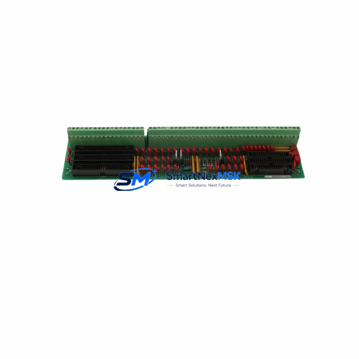
GE DS200TBQDG1AFF Spare for Mark VI Automation: Spare Replacement & Industrial Downtime Risk Control
The GE DS200TBQDG1AFF is an original Extension Terminal Board designed for the GE Mark VI Turbine Control System — one of the most widely deployed DCS platforms in power generation, oil & gas, and heavy industrial facilities worldwide. When this board fails or degrades, the consequences extend far beyond a single I/O channel: the entire turbine control loop may be compromised, triggering unplanned shutdowns, safety interlocks, and costly production losses.
Sourced as an original GE spare, the DS200TBQDG1AFF is pre-tested prior to dispatch and backed by a 12-month warranty. Whether you are executing a planned outage, responding to an emergency fault, or building a strategic spare parts inventory, this board is ready for immediate deployment into your Mark VI control cabinet.
Spare Maintenance Table
| Parameter | Specification / Detail |
|---|---|
| Part Number | DS200TBQDG1AFF |
| Manufacturer | GE (General Electric) |
| Series / Platform | Mark VI Turbine Control System |
| Board Type | Extension Terminal Board |
| Compatibility | GE Mark VI, Mark VIe control racks; VCMI, VTUR, VSVO I/O packs |
| Connector Interface | Multi-pin terminal block; field wiring termination |
| Operating Voltage | 24 VDC (system bus supplied) |
| Operating Temperature | 0°C to +60°C (control cabinet environment) |
| Application Environment | Power generation, oil & gas, petrochemical, heavy industry |
| Installation | DIN rail / rack-mount; direct replacement for existing board |
| Maintenance Recommendation | Inspect terminal connections and ribbon cables annually; replace on first sign of I/O fault or communication error |
| Origin | USA |
| Warranty | 12 Months |
| Pre-shipment Testing | Functional verification performed before dispatch |
Maintenance Planning for Continuous Operation
Maintenance engineers working on GE Mark VI systems understand that the DS200TBQDG1AFF does not operate in isolation. It sits at the intersection of field wiring, I/O signal routing, and the control rack backplane — meaning a fault here can cascade across multiple subsystems. A disciplined maintenance plan should treat this board as part of a broader inspection scope.
During scheduled outages or control cabinet inspections, it is best practice to simultaneously verify the condition of the DS200SDCIG2A power supply module, which provides regulated DC power to the terminal board and adjacent I/O packs. A degraded power supply is a common root cause of intermittent terminal board faults that are misdiagnosed as board failures. Alongside this, the DS200VCMIG2BDB communication interface module (VCMI) should be checked for firmware integrity and connector seating — any communication dropout between the VCMI and the terminal board will generate false I/O alarms.
Field wiring connected to the DS200TBQDG1AFF should be inspected for insulation degradation, loose terminations, and ground faults. In high-vibration environments such as gas turbine enclosures, terminal screws can loosen over time, causing intermittent signal loss. Pairing this inspection with a review of the DS200TCEAG1BDD I/O terminal board and DS200IOCAG1D I/O controller board ensures that the entire signal chain from field device to control processor is verified in a single maintenance window.
For facilities running extended Mark VI installations, the DS200DSPXG1ADB digital signal processor board and DS200EXPSG1ADA expansion power supply are frequently found on the same spare parts checklist as the DS200TBQDG1AFF. These boards share the same rack environment and are subject to the same thermal cycling and vibration stresses. Stocking them together reduces the risk of a secondary failure extending an already costly outage.
Procurement engineers should also consider maintaining a buffer stock of DS200TBCBG1AAA terminal board cables and DS200FCSAG1A flame control system boards where applicable. Ribbon cables and inter-board connectors are consumable items that degrade faster than the boards themselves, and their failure is a leading cause of unnecessary board replacements. Fuse holders and 24 VDC branch circuit protection components within the control cabinet should be inspected and replaced on a fixed-interval basis regardless of apparent condition.
Site Replacement Workflow
Step 1 — Fault Isolation: Before removing the DS200TBQDG1AFF, use the Mark VI HMI diagnostic screens to confirm the fault is localized to the terminal board and not to the upstream I/O pack or downstream field device. Log the active fault codes for post-replacement verification.
Step 2 — Safe Isolation: Follow your site LOTO (Lockout/Tagout) procedure. De-energize the control rack section containing the board. Confirm zero-energy state before opening the cabinet.
Step 3 — Documentation: Photograph the existing wiring layout and terminal assignments before disconnecting any field cables. The DS200TBQDG1AFF uses a fixed terminal block configuration, but field wiring labels may have degraded over years of service.
Step 4 — Board Removal and Replacement: Disconnect field wiring terminals and ribbon cable connectors. Remove the board from the rack. Install the replacement DS200TBQDG1AFF, reconnect all cables in the documented sequence, and verify terminal torque to manufacturer specification.
Step 5 — System Verification: Re-energize the rack section. Monitor the Mark VI HMI for I/O status confirmation. Clear active faults and verify all associated I/O channels return to normal state. Document the replacement in your maintenance management system (CMMS).
This workflow is compatible with both like-for-like replacement of the DS200TBQDG1AFF and cross-reference substitution from legacy Mark V terminal board configurations. The board’s direct-replacement design eliminates the need for software reconfiguration in standard swap scenarios, minimizing total downtime to the physical replacement window.
Spare Parts Support FAQ
Q1: What is the shelf life of the DS200TBQDG1AFF in storage, and how should it be stored?
When stored in original anti-static packaging in a climate-controlled environment (15°C–25°C, relative humidity below 60%), the DS200TBQDG1AFF has an effective shelf life of 5–10 years. Inspect storage stock annually for connector oxidation and packaging integrity. Rotate stock on a first-in, first-out basis.
Q2: How is compatibility with my specific Mark VI rack configuration verified before shipment?
Provide your full rack configuration details — including VCMI firmware version, I/O pack types, and existing terminal board revision suffix — at the time of order. Our technical team cross-references this against the DS200TBQDG1AFF revision matrix to confirm compatibility before dispatch. All units undergo functional testing prior to shipment.
Q3: Can the DS200TBQDG1AFF replace older Mark V terminal board variants in a system upgrade scenario?
Direct substitution from Mark V to Mark VI terminal boards requires a system-level compatibility assessment, as the backplane connector pinouts and communication protocols differ between generations. Contact our technical support team with your existing board part number and rack configuration for a formal cross-reference evaluation before ordering.
Q4: What does the 12-month warranty cover, and what is the claims process?
The 12-month warranty covers manufacturing defects and functional failures under normal operating conditions. It does not cover damage resulting from incorrect installation, overvoltage events, or physical mishandling. To initiate a warranty claim, contact our support team with your order number, fault description, and site installation photos. Replacement or repair is processed within 5–10 business days of claim approval.
© 2026 SMARTNEXMSK. All rights reserved.
Original Source: https://smartnexmsk.com
Contact: [email protected] | +86 18259474341