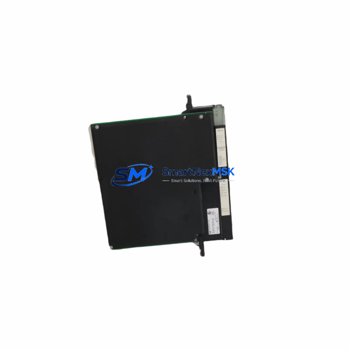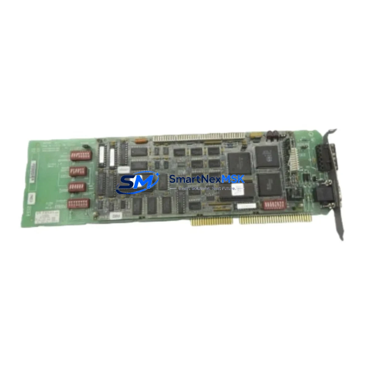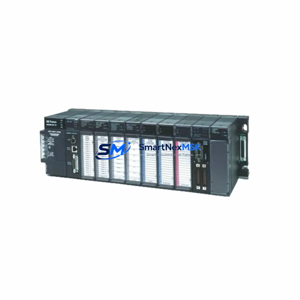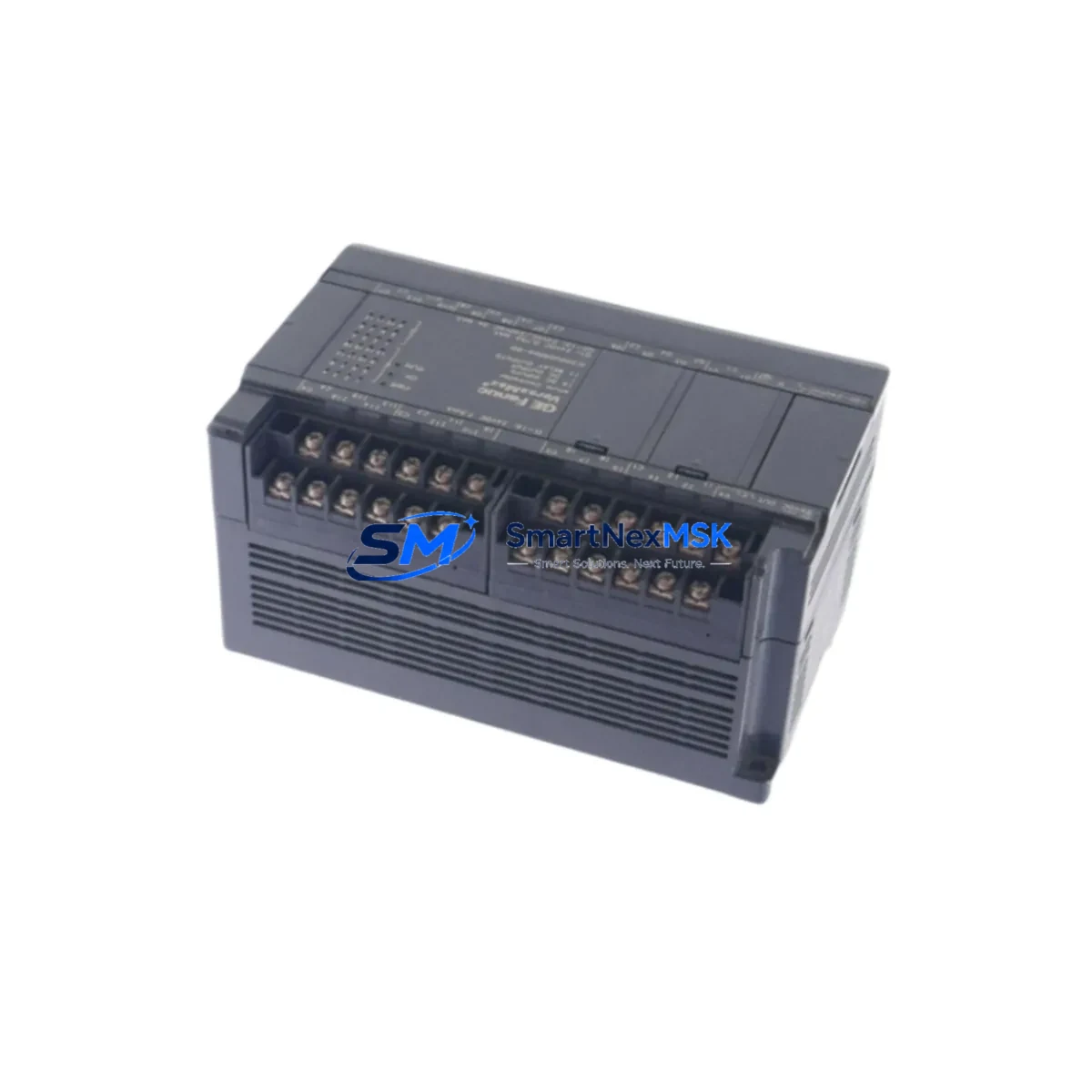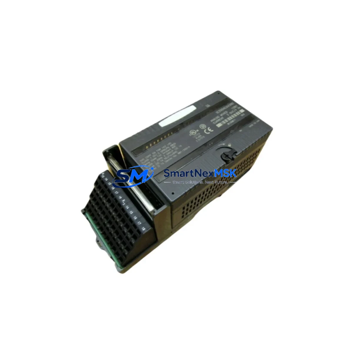
GE Fanuc IC200ALG430 Maintenance-Ready Spare for VersaMax Automation
The GE Fanuc IC200ALG430 is an original analog mixed I/O module designed for the VersaMax Micro and VersaMax modular PLC platform. As a maintenance-ready spare, it supports rapid replacement in production environments where analog signal integrity is critical to continuous operation. Featuring 4 analog inputs and 2 analog outputs, this module handles both current (4–20 mA) and voltage (0–10 V) signal types, making it a versatile component in process control, machine automation, and legacy system upkeep.
For maintenance engineers managing aging GE Fanuc VersaMax installations, the IC200ALG430 is a high-priority spare. Unplanned downtime caused by analog I/O failure can cascade across entire control loops — affecting PID regulation, sensor feedback, and actuator command chains. Stocking a verified original replacement eliminates the diagnostic delay caused by sourcing uncertainty and ensures that field replacement can be completed within a single maintenance window.
Procurement engineers sourcing this module should confirm compatibility with the existing VersaMax backplane (IC200CHS002, IC200CHS005, or IC200CHS022) and verify that the system firmware version supports the module’s configuration profile. All units supplied by SMARTNEXMSK are tested prior to shipment and covered by a 12-month warranty, providing documented assurance for both planned and emergency procurement cycles.
Spare Maintenance Table
| Parameter | Specification |
|---|---|
| Part Number | IC200ALG430 |
| Brand | GE Fanuc |
| Series | VersaMax Modular PLC |
| Module Type | Analog Mixed I/O (4AI / 2AO) |
| Input Signal Range | 0–10 V / 4–20 mA (selectable per channel) |
| Output Signal Range | 0–10 V / 4–20 mA (selectable per channel) |
| Resolution | 12-bit |
| Power Consumption | Supplied via VersaMax backplane bus |
| Operating Temperature | 0°C to 60°C |
| Backplane Compatibility | IC200CHS002, IC200CHS005, IC200CHS022 |
| Installation | DIN rail / panel mount via VersaMax carrier |
| Condition | Original, tested before shipment |
| Warranty | 12 Months |
| Origin | United States |
Maintenance Planning for Continuous Operation
When replacing the IC200ALG430 in a live VersaMax system, a thorough inspection of the surrounding electrical environment is essential to prevent repeat failures and ensure stable recommissioning. Maintenance engineers should begin by verifying the 24 VDC backplane power supply — typically sourced from a dedicated power module such as the IC200PWR002 or IC200PWR101 — to confirm that supply voltage is within tolerance before inserting the new module.
Analog signal wiring should be inspected at the terminal block level. Shielded twisted-pair cables must be properly grounded at a single point to prevent ground loops that corrupt 4–20 mA signals. If the system uses signal isolators or signal conditioners between field instruments and the IC200ALG430, these components — including DIN-rail-mounted signal isolators and loop-powered transmitter barriers — should be tested for drift or failure before the replacement module is powered up.
The VersaMax CPU module (such as the IC200CPUE05 or IC200UAL006) should be checked for active fault codes related to the analog I/O rack. After module replacement, a forced I/O test should be performed to verify that all four input channels and both output channels respond correctly to calibrated signal sources. If the system includes a VersaMax Network Interface Unit (NIU) such as the IC200BEM003 for Profibus or DeviceNet communication, confirm that the module address and I/O map remain consistent with the CPU configuration after the swap.
For control cabinets running mixed analog and digital I/O, it is advisable to simultaneously inspect adjacent digital I/O modules (IC200MDL640, IC200MDL730) for signs of contact wear or terminal corrosion, as these faults often co-occur with analog module degradation in high-cycle environments. Relay output modules in the same cabinet — such as the IC200MDL940 — should also be checked for coil resistance and contact integrity during the same maintenance window.
Where the VersaMax system interfaces with an HMI — such as a QuickPanel or third-party operator panel connected via serial or Ethernet — verify that the HMI tag database correctly reflects the analog channel configuration after the module replacement. Discrepancies in scaling or engineering unit mapping can cause false alarms or incorrect process displays that delay return-to-service.
Site Replacement Workflow
Step 1 — Pre-Replacement Verification: Document the existing module’s channel configuration, signal type (voltage/current), and scaling parameters from the PLC programming software (Proficy Machine Edition or equivalent). Export the current I/O configuration as a backup before any hardware change.
Step 2 — Safe Isolation: Place the VersaMax CPU in STOP mode. De-energize the analog field circuits at the source — do not rely solely on the PLC output disable. Verify zero-energy state with a calibrated multimeter before disconnecting field wiring from the terminal block.
Step 3 — Module Removal: Release the module locking tab on the VersaMax carrier and slide the IC200ALG430 out of the backplane slot. Inspect the backplane connector pins for damage or contamination before inserting the replacement unit.
Step 4 — Replacement Installation: Insert the new IC200ALG430 into the same backplane slot. Reconnect field wiring in the original terminal sequence. Confirm that shielding is re-terminated correctly.
Step 5 — Recommissioning: Power up the system and place the CPU in RUN mode. Monitor analog input values against known process references to confirm correct signal scaling. Verify analog output channels by commanding known values and measuring the resulting field signal with a calibrated instrument.
Step 6 — Documentation: Record the replacement date, new module serial number, and post-replacement test results in the site maintenance log. Update the spare parts inventory to reflect the consumed unit and initiate a reorder to maintain minimum stock levels.
Spare Parts Support FAQ
Q1: Is the IC200ALG430 compatible with all VersaMax backplane configurations?
The IC200ALG430 is compatible with standard VersaMax modular backplanes including the IC200CHS002 (5-slot), IC200CHS005 (8-slot), and IC200CHS022 (10-slot). It is not designed for the VersaMax Micro (IC200UDR series) fixed-I/O controllers. Always verify the backplane model and available slot count before ordering.
Q2: What testing is performed before shipment?
Each IC200ALG430 unit supplied by SMARTNEXMSK undergoes functional verification including power-on self-test, analog input channel signal response check across the full 4–20 mA and 0–10 V ranges, and analog output channel load test. Units that do not pass all test criteria are not shipped. A 12-month warranty is provided from the date of shipment.
Q3: Can this module replace an older IC200ALG430 revision without reprogramming?
In most cases, yes. GE Fanuc maintained backward hardware compatibility across IC200ALG430 revisions. However, if the installed Proficy Machine Edition project was configured for a specific hardware revision, a hardware catalog update may be required. SMARTNEXMSK recommends confirming the firmware version of the replacement unit against the project’s hardware configuration before final commissioning.
Q4: What is the recommended spare parts stocking strategy for VersaMax analog I/O?
For production facilities running VersaMax-based control systems, a minimum of one IC200ALG430 per installed system is recommended as a cold spare. Sites with multiple VersaMax racks or high-cycle analog applications should maintain two units. Given the end-of-life status of the VersaMax platform, long-term supply availability cannot be guaranteed from OEM channels — sourcing from a specialist supplier with verified stock and a documented warranty policy is the most reliable strategy for multi-year maintenance planning.
© 2026 SMARTNEXMSK. All rights reserved.
Original Source: https://smartnexmsk.com
Contact: [email protected] | +86 18259474341