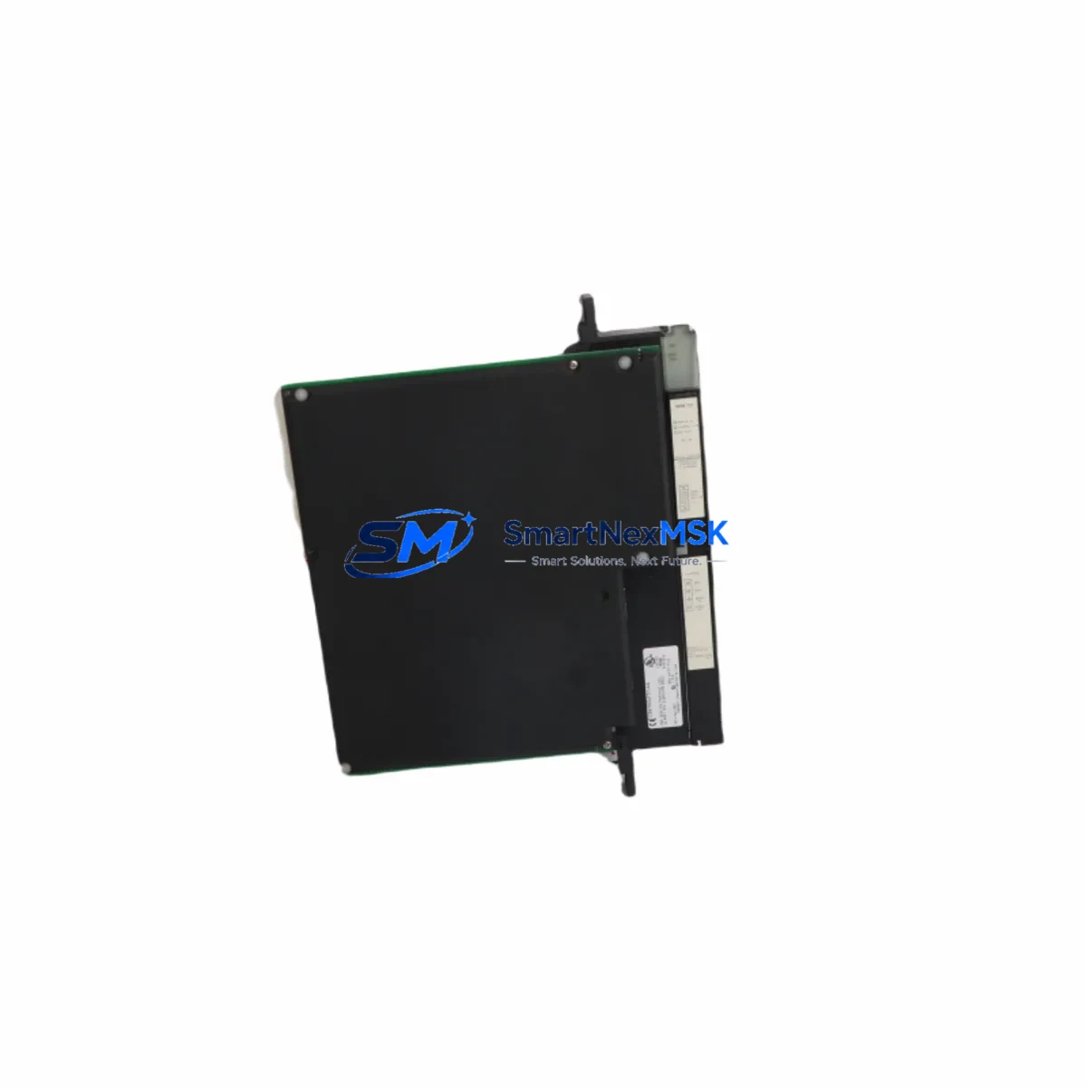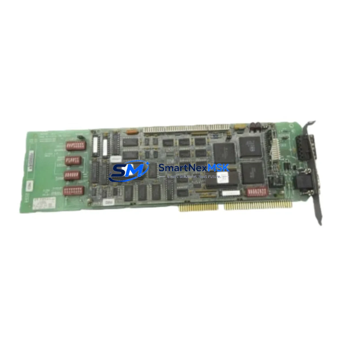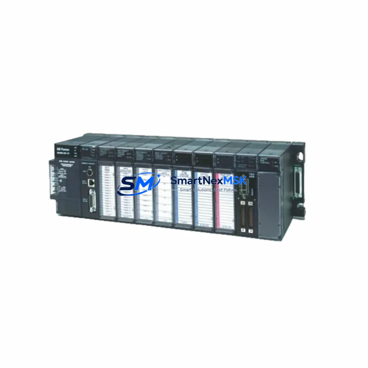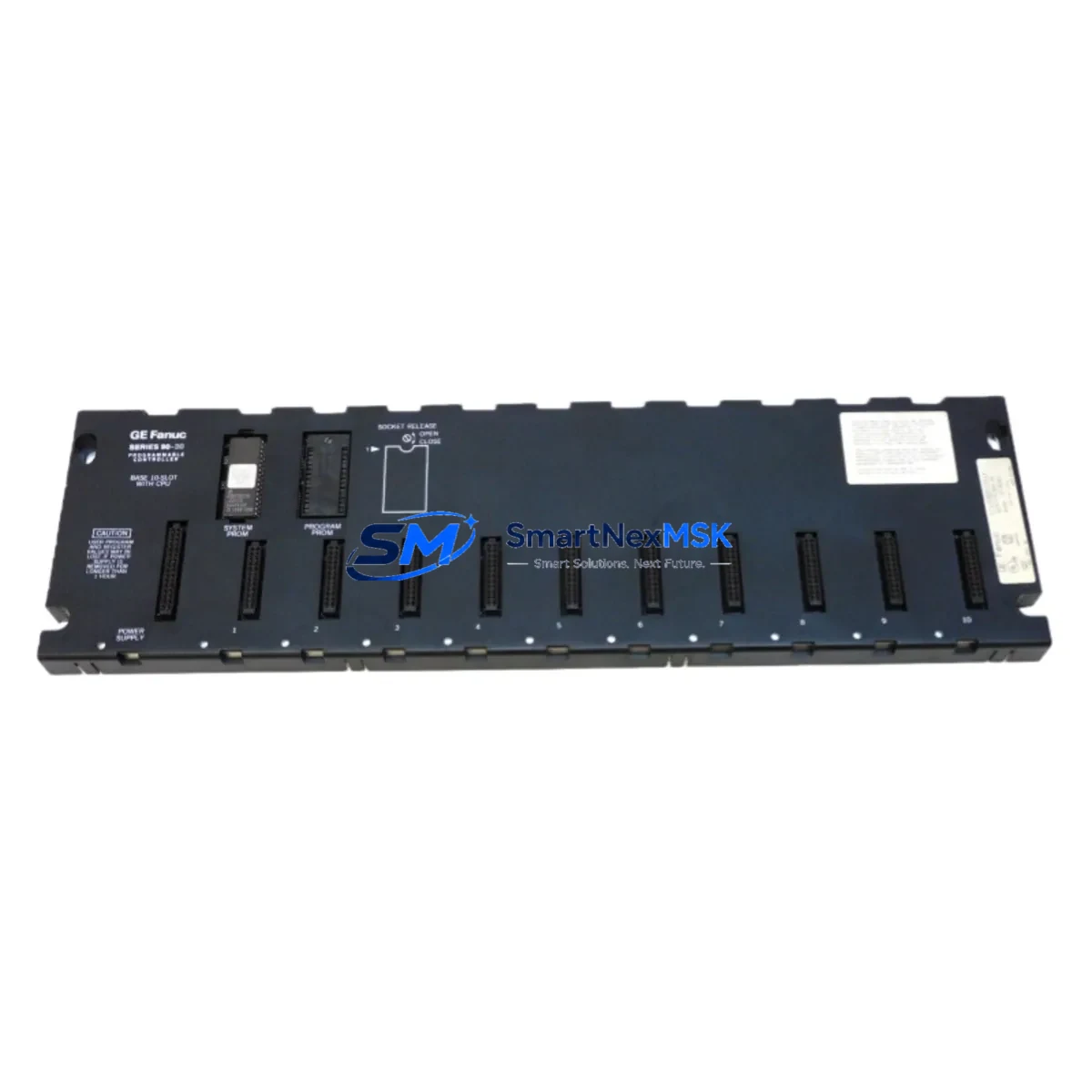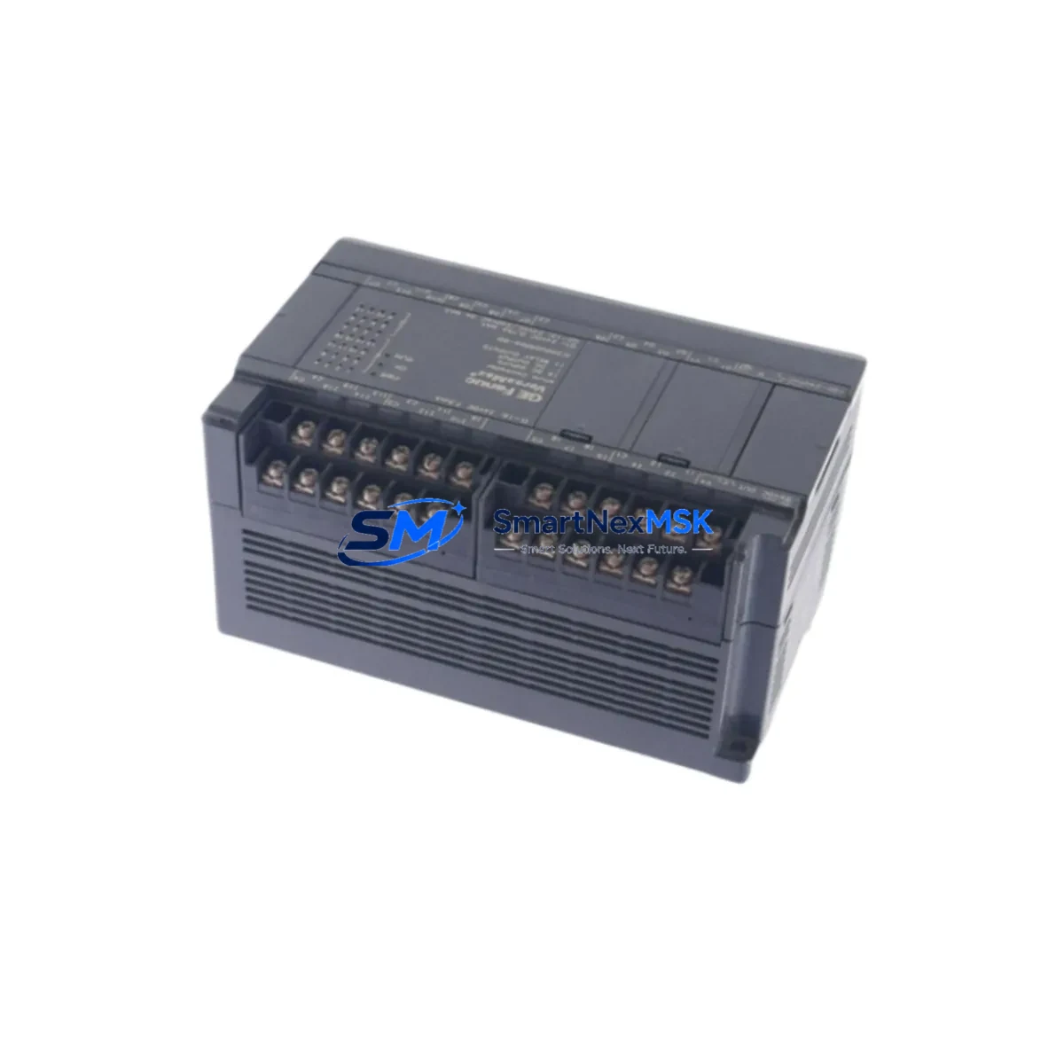
GE Fanuc IC200UDR005 Retrofit-Ready Relay Output Module: Seamless Compatibility for Legacy VersaMax Micro Control Systems
The GE Fanuc IC200UDR005 is a 28-point combination I/O module featuring 16 DC inputs and 12 relay outputs, purpose-built for the VersaMax Micro PLC platform. As production lines age and original equipment manufacturers discontinue legacy components, the IC200UDR005 has become one of the most sought-after retrofit and replacement modules for facilities running GE Fanuc VersaMax Micro controllers. Whether you are restoring a failed unit, upgrading a control cabinet, or migrating from an older GE Series 90 Micro architecture, this module provides a verified drop-in solution with no firmware modification required in most standard configurations.
SMARTNEXMSK maintains ready stock of the IC200UDR005 sourced from authorized distribution channels and tested prior to shipment. Each unit ships with a 12-month warranty covering manufacturing defects and functional failures under normal operating conditions. Our technical team supports pre-sale compatibility verification and post-installation commissioning guidance for retrofit projects of any scale.
Upgrade Compatibility Table
| Parameter | IC200UDR005 Specification | Retrofit Notes |
|---|---|---|
| I/O Configuration | 16 DC Inputs / 12 Relay Outputs (28-point) | Verify field wiring matches relay output terminal assignments before swap |
| Supply Voltage | 24 VDC nominal | Confirm existing power supply (e.g. IC200PWR002 or equivalent) delivers stable 24 VDC ±10% |
| Backplane Interface | VersaMax Micro local bus | Compatible with IC200UEX series expansion units; verify slot addressing in programmer |
| Communication Compatibility | Serial RS-232 / RS-485 via IC200USB001 or IC200CBL001 programming cable | Retain existing program via Machine Edition or Proficy ME before module swap |
| Replacement Candidates | IC200UDR005-CA, IC200UDR005-AE (earlier revisions) | Firmware revision differences are backward-compatible in most VersaMax Micro CPU configurations |
| Installation Requirement | DIN rail or panel mount; standard VersaMax Micro form factor | No mechanical modification required for direct chassis swap |
| Commissioning Focus | I/O forcing, output coil verification, scan cycle confirmation | Use Proficy Machine Edition to verify I/O table mapping post-installation |
| Warranty | 12 Months | Covers manufacturing defects and functional failures under rated operating conditions |
Retrofit Planning for Existing Automation Systems
Successful retrofit of the IC200UDR005 into an existing VersaMax Micro control system requires a structured pre-installation review. Begin by auditing the current control cabinet layout: confirm the power supply module — typically an IC200PWR002 or IC200PWR001 — is delivering adequate current capacity for the replacement module alongside any co-installed I/O expansion units such as the IC200UEX011 or IC200UEX016. Insufficient power headroom is one of the most common causes of intermittent faults after a module swap.
Next, document the existing terminal wiring. The IC200UDR005 uses a 40-pin connector block; verify that field device wiring — sensors, solenoids, motor starters, and indicator lamps — aligns with the relay output terminal map in GE publication GFK-1504. Pay particular attention to common terminal groupings for relay outputs, as incorrect common wiring can cause output coil conflicts or blown fuses on the first power-up.
For systems that include a VersaMax Micro CPU module such as the IC200CPUE05 or IC200CPUE05-AE, back up the existing ladder logic program using Proficy Machine Edition or the legacy VersaMax Programming Software before removing the old module. Store the program file with a timestamped revision note. If the control system also interfaces with an HMI panel — for example a QuickPanel or a third-party Weintek or Proface display — capture all HMI screen tag bindings and communication port settings (baud rate, parity, station address) before disconnecting any RS-232 or RS-485 links.
Where the VersaMax Micro system communicates upstream to a SCADA or DCS via a GE Ethernet Interface module such as the IC200ETM001, confirm that the IP address configuration and Modbus TCP or SRTP protocol settings are documented. These settings reside in the CPU configuration, not the I/O module, but a full system restart after the module swap will re-initialize all communication links and any undocumented settings may be lost.
If the retrofit involves expanding I/O capacity beyond the base IC200UDR005 configuration, consider adding an IC200UEX011 discrete expansion module or an IC200ALG320 analog input module to the same VersaMax Micro rack. Both are compatible with the local bus architecture and can be addressed within the same I/O table without requiring a new CPU program structure — only an I/O configuration update in the programmer is needed.
Finally, label all terminal connections before disconnection, photograph the existing wiring layout, and prepare a rollback plan that includes the original module (if repairable) or a pre-configured spare. This discipline is especially important in continuous-process environments where unplanned downtime carries significant production cost.
Downtime Control During System Migration
Minimizing downtime during a VersaMax Micro module replacement begins with preparation, not execution. The physical swap of the IC200UDR005 typically takes under 15 minutes for a trained technician; the majority of migration time is consumed by pre-swap verification, program backup, and post-swap commissioning. Structured preparation compresses total downtime to a predictable window that can be scheduled during a planned maintenance shift.
Before the maintenance window opens, pre-stage the replacement IC200UDR005 on a bench and verify its revision label matches or supersedes the unit being replaced. If the facility uses a hot-standby or redundant control architecture — for example, a dual-CPU VersaMax Micro configuration with an IC200CPUE05 in each rack — coordinate the switchover sequence so the standby CPU assumes control before the primary rack is de-energized. This eliminates process interruption entirely for redundant systems.
For single-CPU systems, communicate the planned outage window to all affected departments. Place the CPU in STOP mode via Proficy Machine Edition, force all outputs to their safe state (typically de-energized), and then de-energize the control cabinet. Swap the module, re-energize, and perform a controlled RUN mode transition while monitoring the I/O status display in the programmer. Verify each output coil individually using the I/O forcing function before releasing the system to automatic operation.
Retain the original program logic unchanged during the initial post-swap commissioning phase. Do not modify ladder rungs, timer presets, or counter values until the system has completed at least one full production cycle under observation. This preserves the original control logic as a verified baseline and isolates any post-swap anomalies to the hardware replacement rather than a software change.
SMARTNEXMSK ships all IC200UDR005 units with a pre-shipment functional test report. Each module is powered, I/O-exercised, and verified against GE Fanuc factory acceptance criteria before dispatch. This reduces the risk of receiving a non-functional unit and eliminates the need for incoming inspection in most retrofit scenarios.
Retrofit Support FAQ
Q1: Is the IC200UDR005 a direct drop-in replacement for earlier VersaMax Micro relay output modules?
Yes. The IC200UDR005 is backward-compatible with earlier VersaMax Micro relay output configurations including the IC200UDR005-CA and IC200UDR005-AE revisions. The module uses the same 40-pin connector block, identical backplane interface, and the same I/O table addressing structure. No CPU program modification is required in standard configurations. Verify the CPU firmware revision is GFK-1504 Rev. D or later for full feature compatibility.
Q2: What commissioning steps are required after installing the IC200UDR005?
After physical installation, connect the programming cable (IC200CBL001 or IC200USB001) and open the existing program in Proficy Machine Edition. Perform an I/O configuration download if the module revision differs from the original. Place the CPU in RUN mode and use the I/O forcing function to verify each of the 12 relay output coils and 16 DC input channels individually. Confirm scan cycle time is within the expected range and check for any I/O fault codes in the CPU status display before releasing to automatic operation.
Q3: Can the IC200UDR005 be used in a system that also includes analog I/O modules?
Yes. The VersaMax Micro platform supports mixed discrete and analog I/O configurations. The IC200UDR005 occupies discrete I/O address space and does not conflict with analog modules such as the IC200ALG320 (analog input) or IC200ALG430 (analog output) installed in the same rack or expansion chassis. Verify the total I/O point count does not exceed the CPU’s supported I/O capacity as specified in GFK-1504.
Q4: What does the 12-month warranty cover, and how is a warranty claim processed?
The 12-month warranty covers manufacturing defects and functional failures under rated operating conditions (24 VDC supply, ambient temperature within GE Fanuc specifications, and correct installation per GFK-1504). It does not cover damage from incorrect wiring, overvoltage, physical impact, or unauthorized modification. To initiate a warranty claim, contact SMARTNEXMSK at [email protected] with the order number, module serial number, and a description of the fault. Replacement units are dispatched within 3 business days of claim verification.
© 2026 SMARTNEXMSK. All rights reserved.
Original Source: https://smartnexmsk.com
Contact: [email protected] | +86 18259474341