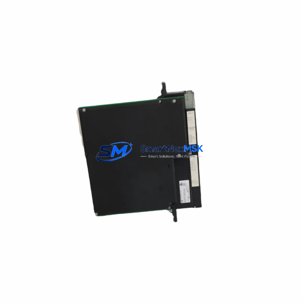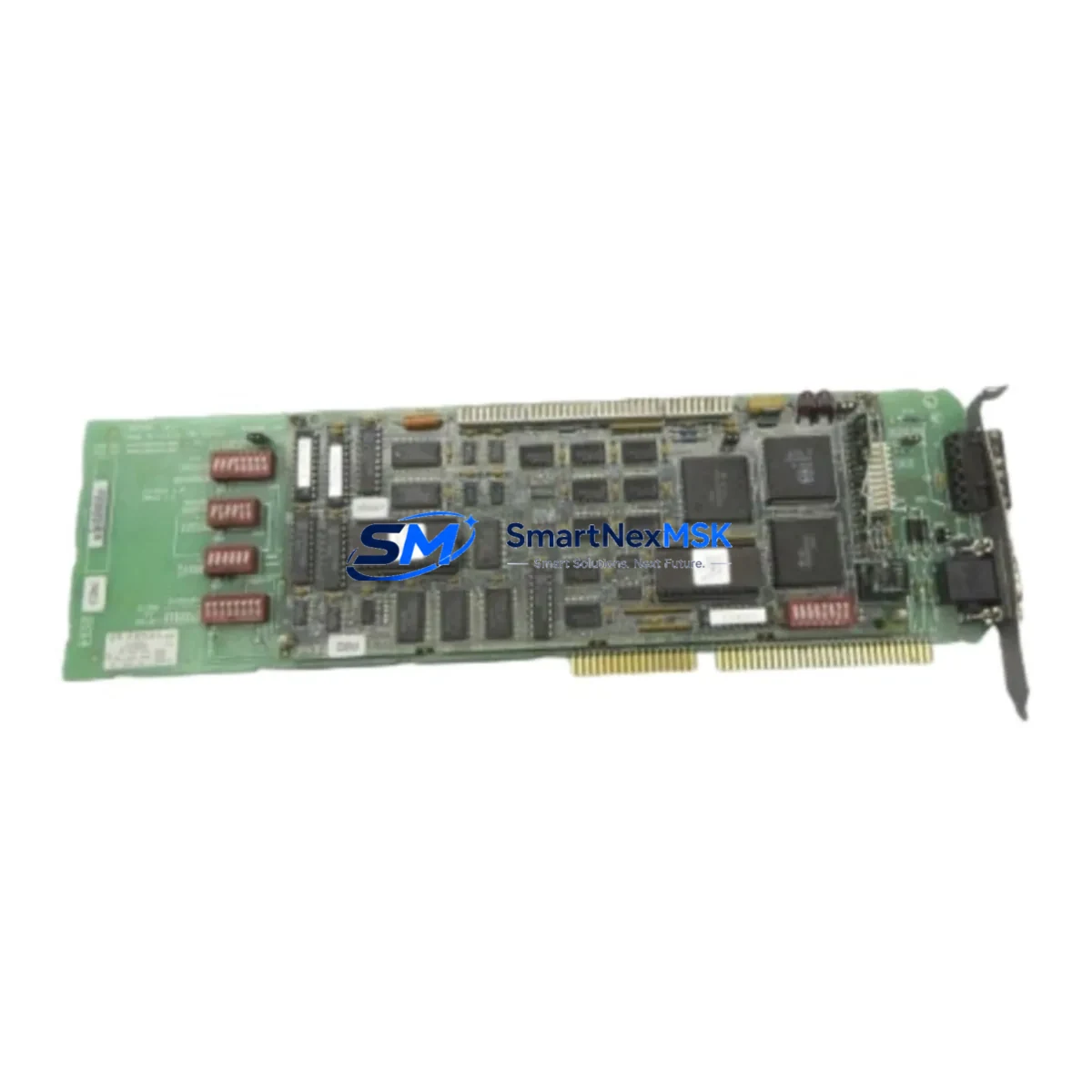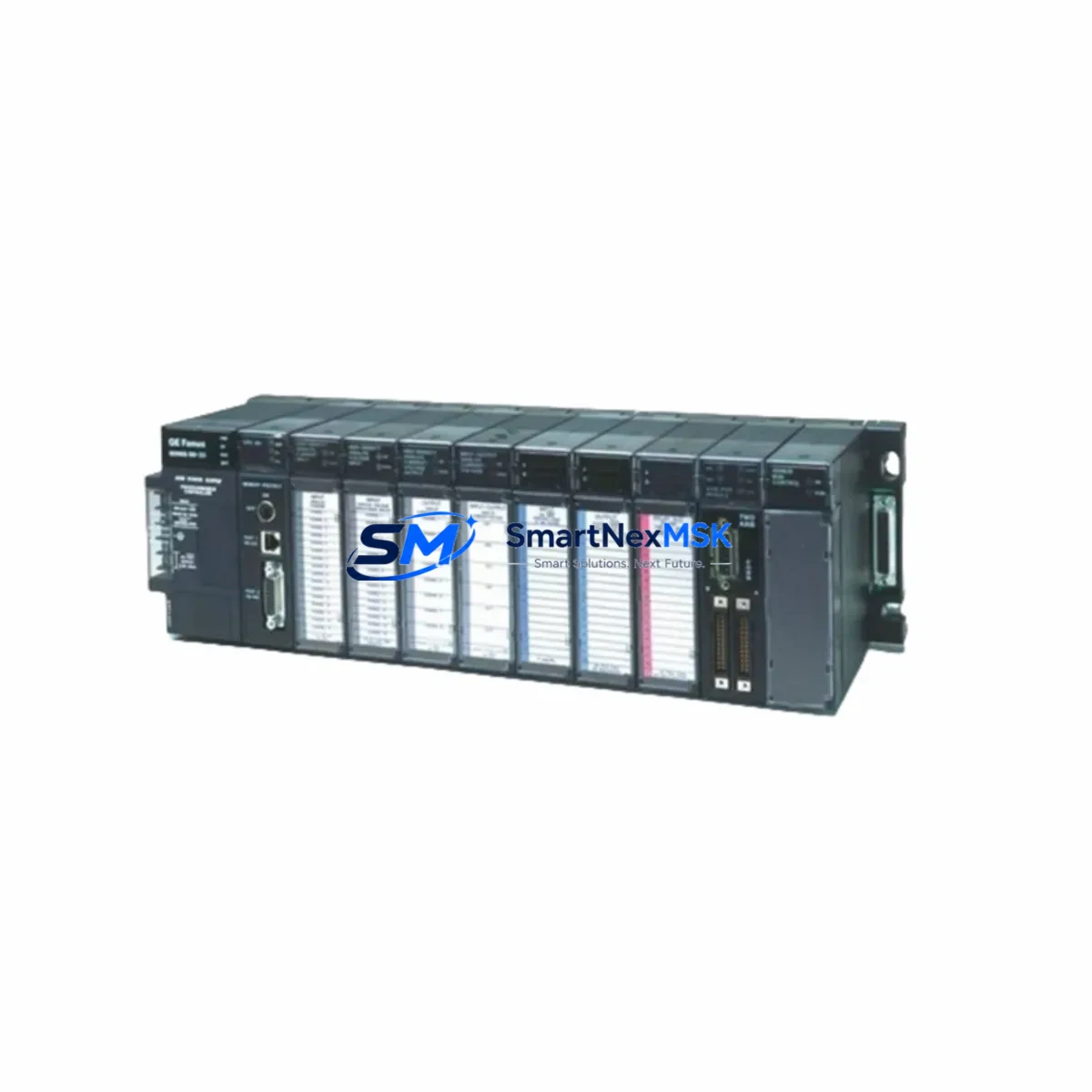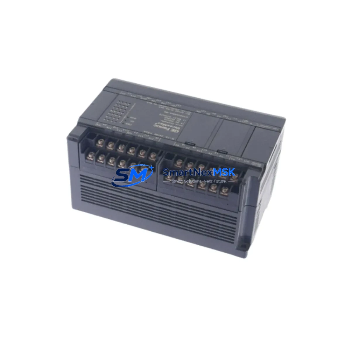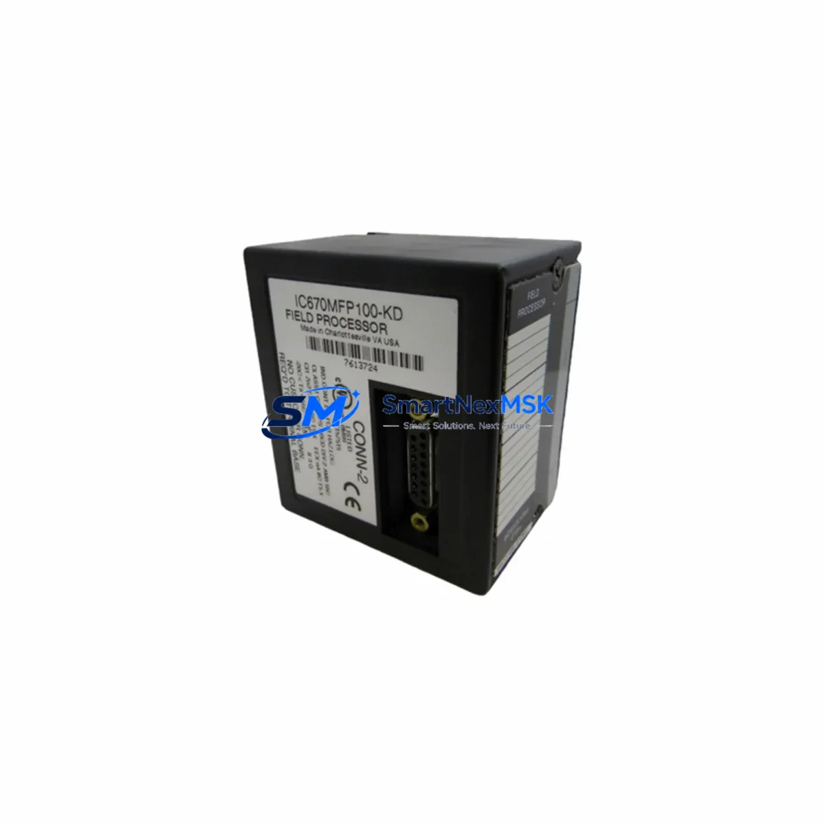
GE Fanuc IC670MFP100 Maintenance-Ready Spare for Series 90 Micro Automation
The GE Fanuc IC670MFP100 is a critical processor module within the Series 90 Micro PLC platform — a compact yet powerful controller widely deployed across discrete manufacturing, packaging lines, material handling systems, and light industrial automation cells. When this module fails or degrades, the entire control loop is at risk. Unplanned downtime in these environments can cost thousands of dollars per hour, making a verified, maintenance-ready spare an essential line item in any responsible spare parts inventory strategy.
At SMARTNEXMSK, we supply the IC670MFP100 as an original spare, fully tested prior to shipment and backed by a 12-month warranty. Our stock is sourced through verified industrial channels, and each unit undergoes functional verification to confirm logic execution, I/O communication, and power rail integrity before dispatch. Whether you are responding to an emergency breakdown or executing a planned preventive maintenance cycle, we can support same-day quotation and rapid international shipping.
The IC670MFP100 serves as the CPU and program execution core of the Series 90 Micro system. It manages ladder logic execution, handles local I/O scanning, and coordinates communication with expansion modules and HMI devices. Its failure mode is typically sudden — often triggered by power transients, excessive ambient temperature, or accumulated capacitor degradation in aging installations. Maintenance engineers should treat this module as a high-priority spare in any facility running GE Fanuc Series 90 Micro controllers, particularly in systems that have been in continuous service for more than five years.
Spare Maintenance Table
| Parameter | Specification / Detail |
|---|---|
| Part Number / SKU | IC670MFP100 |
| Brand | GE Fanuc (now part of Emerson / Proficy portfolio) |
| Series | Series 90 Micro PLC |
| Module Type | CPU / Processor Module |
| Supply Voltage | 24 VDC (nominal) |
| Program Memory | 6 KB (ladder logic) |
| I/O Points (onboard) | Up to 28 discrete I/O (expandable via expansion modules) |
| Communication Port | RS-485 serial (SNP/SNP-X protocol) |
| Operating Temperature | 0°C to 55°C |
| Mounting | DIN rail or panel mount |
| Compatibility | Series 90 Micro expansion racks, IC670 family I/O modules |
| Condition | Original spare, pre-shipment tested |
| Warranty | 12 months from date of shipment |
| Lead Time | In stock — same-day quotation available |
| Application Environment | Discrete manufacturing, packaging, material handling, light industrial |
| Maintenance Recommendation | Replace proactively at 7–10 year service interval or upon first fault indication |
Maintenance Planning for Continuous Operation
Replacing the IC670MFP100 in a live production environment requires more than simply swapping the CPU module. A disciplined maintenance engineer will use this replacement event as an opportunity to audit the entire control cabinet and associated electrical circuit. The following components should be inspected, tested, or replaced concurrently to prevent repeat failures and ensure the system returns to full operational reliability.
Begin with the 24 VDC power supply module feeding the Series 90 Micro base unit. Power supply degradation is one of the leading causes of CPU module failure — a supply operating outside its regulation band will stress the processor’s internal voltage regulators over time. Verify output voltage under load and check for ripple using a multimeter or oscilloscope. If the supply is more than five years old, consider replacing it alongside the IC670MFP100 as a matched pair.
Next, inspect the IC670MDL640 or IC670MDL740 discrete input modules installed in the expansion slots. These 24 VDC digital input modules share the same backplane bus as the CPU and can introduce noise or bus contention if their input filter capacitors have degraded. Check for sticky inputs, intermittent signal loss, or LED indicators that do not match field device states.
The IC670MDL930 discrete output module should also be evaluated. Output modules driving inductive loads — solenoids, motor starters, relay coils — are subject to back-EMF stress. Inspect for burned output channels, verify suppression diodes or RC snubbers on inductive loads, and confirm that output current ratings have not been exceeded by field wiring changes made since original commissioning.
Review the RS-485 serial communication wiring between the IC670MFP100 and any connected HMI panels or SCADA gateways. Loose termination resistors, incorrect cable shielding, or ground loops on the communication bus can cause the CPU to report communication faults even after a successful module replacement. Re-terminate all RS-485 connections and verify bus impedance before restarting the system.
If the installation includes analog I/O modules such as the IC670ALG230 (analog input) or IC670ALG320 (analog output), calibrate these modules after the CPU replacement. Program memory restoration from a backup may not preserve analog scaling parameters if the original configuration was not fully documented. Verify 4–20 mA loop integrity and confirm that signal isolators or barriers in the analog circuit are functioning within specification.
For cabinets with terminal blocks and field wiring, inspect all screw terminals for corrosion, loose connections, or thermal discoloration — signs of sustained overcurrent or poor contact resistance. Tighten all terminals to manufacturer torque specifications and replace any discolored or brittle wire insulation. This step is frequently overlooked during emergency replacements and is a common source of repeat faults within weeks of a CPU swap.
Finally, if the facility uses a programming terminal or laptop running GE Proficy Machine Edition for ladder logic upload and download, verify that the software version is compatible with the IC670MFP100 firmware revision. Confirm that a current, verified backup of the application program exists before powering down the system for module replacement. A missing or corrupted program backup can extend a planned 30-minute replacement into a multi-hour recovery event.
Site Replacement Workflow
Step 1 — Pre-Replacement Preparation: Back up the existing ladder logic program using GE Proficy Machine Edition or the legacy Logicmaster 90 Micro software. Document all I/O addresses, communication parameters, and analog scaling values. Photograph the wiring layout inside the control cabinet before disconnecting any terminals.
Step 2 — Safe Isolation: Follow your facility’s lockout/tagout (LOTO) procedure. De-energize the 24 VDC supply to the Series 90 Micro base unit. Confirm zero voltage at the power supply output terminals before proceeding.
Step 3 — Module Removal: Disconnect the RS-485 communication cable and any programming port connections from the IC670MFP100. Release the module retention latch and slide the CPU module out of the base unit. Handle the replacement IC670MFP100 with appropriate ESD precautions — use a grounded wrist strap and anti-static packaging.
Step 4 — Installation and Configuration: Insert the new IC670MFP100 into the base unit slot. Reconnect the RS-485 communication cable and programming port. Restore power and confirm that the module powers up without fault LEDs. Download the backed-up application program and verify I/O mapping matches the field wiring.
Step 5 — Functional Verification: Cycle through all discrete inputs and outputs to confirm correct operation. Verify analog channel readings against known reference signals. Confirm HMI communication is restored and that all operator screens display correct process values. Document the replacement in the facility’s maintenance log with the new module serial number and date of installation.
This structured workflow minimizes the risk of secondary faults, reduces total downtime, and ensures the replacement IC670MFP100 is fully integrated into the control system before returning the process to automatic operation.
Spare Parts Support FAQ
Q1: Is the IC670MFP100 still available as a new original spare, or only as a refurbished unit?
SMARTNEXMSK supplies the IC670MFP100 as an original spare sourced through verified industrial distribution channels. Each unit is individually tested prior to shipment. While GE Fanuc has transitioned the Series 90 Micro line to legacy support status, original stock remains available through specialist industrial suppliers. We recommend securing at least one spare unit per installed system to protect against extended lead times as global stock diminishes.
Q2: How do I confirm compatibility between the IC670MFP100 and my existing Series 90 Micro expansion modules?
The IC670MFP100 is compatible with all IC670 family expansion modules, including discrete input/output modules and analog I/O modules designed for the Series 90 Micro platform. Compatibility is determined by the base unit type and firmware revision. Provide your existing base unit model number and firmware version when placing your order, and our technical team will confirm compatibility before shipment.
Q3: What testing is performed on each IC670MFP100 before shipment?
Each unit undergoes power-on functional testing to verify CPU initialization, I/O bus communication, and serial port operation. Units that fail any test parameter are quarantined and not shipped. A test report is available upon request. All shipped units are covered by a 12-month warranty from the date of shipment, covering defects in materials and workmanship under normal operating conditions.
Q4: What is the recommended spare parts inventory strategy for facilities running multiple Series 90 Micro systems?
For facilities with two or more Series 90 Micro installations, we recommend maintaining a minimum of one IC670MFP100 CPU module per three installed systems, plus one spare 24 VDC power supply and one spare discrete I/O module of each type in use. This buffer inventory supports rapid response to unplanned failures without waiting for international shipping lead times. SMARTNEXMSK offers volume pricing and reserved stock agreements for facilities with ongoing maintenance requirements.
© 2026 SMARTNEXMSK. All rights reserved.
Original Source: https://smartnexmsk.com
Contact: [email protected] | +86 18259474341