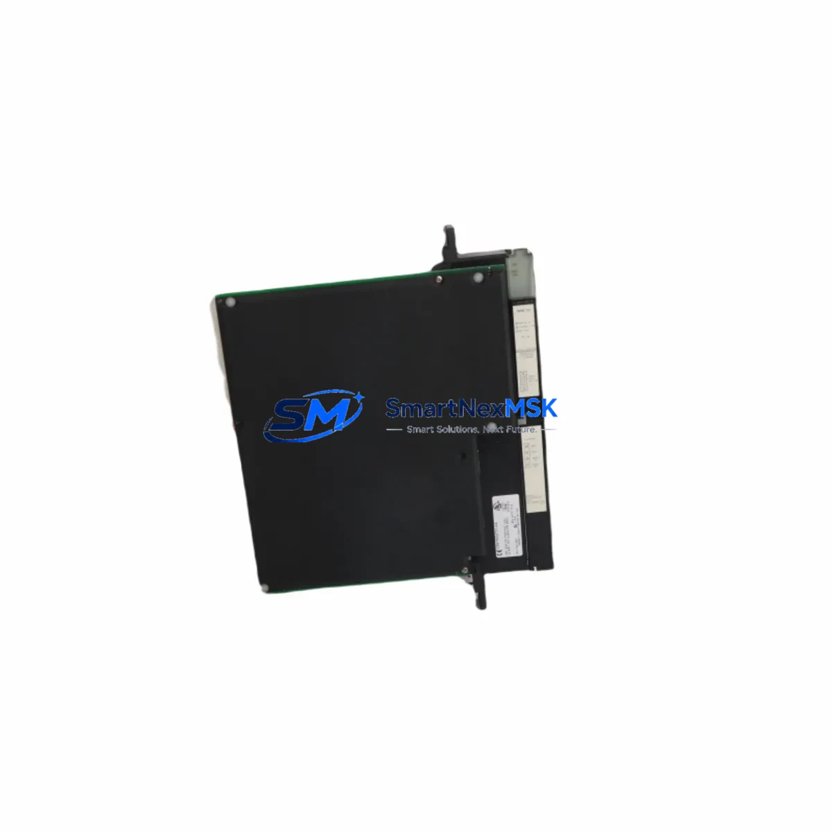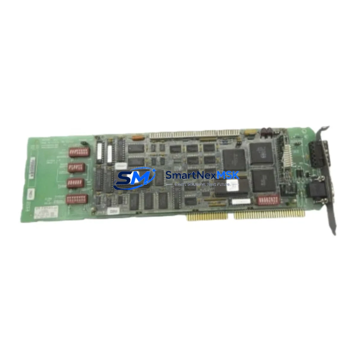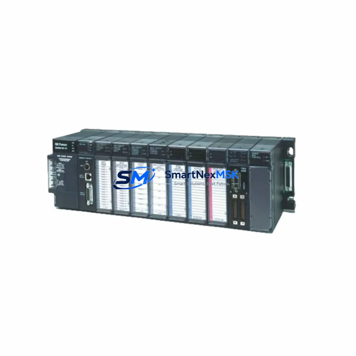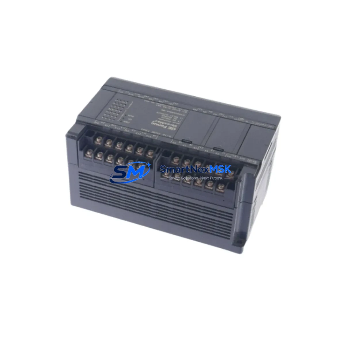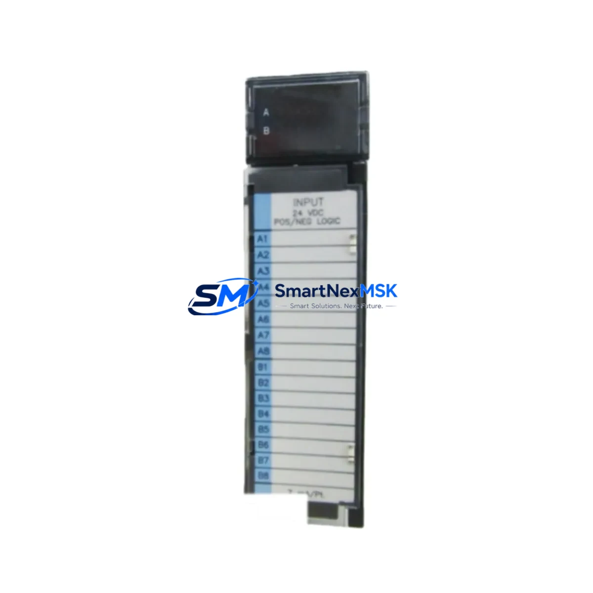
GE Fanuc IC693MDL640 Maintenance-Ready Spare for Series 90-30 Automation
The GE Fanuc IC693MDL640 is a 16-point, 24VDC discrete input module designed for the Series 90-30 PLC platform — one of the most widely deployed programmable logic controller families in industrial automation. For maintenance engineers managing aging control systems, securing a verified original spare of the IC693MDL640 is a critical step in any downtime-prevention strategy. Whether you are conducting a scheduled annual inspection, responding to an unplanned I/O fault, or building a site-level spare parts inventory, this module delivers the electrical compatibility and form-factor accuracy required for direct slot replacement without system reconfiguration.
Each IC693MDL640 unit shipped by SMARTNEXMSK undergoes pre-shipment functional verification, including input channel continuity checks, backplane connector inspection, and LED indicator validation. The module is packaged in anti-static protective material and ships with a 12-month warranty covering manufacturing defects and functional failures under normal operating conditions.
Spare Maintenance Table
| Parameter | Specification |
|---|---|
| Part Number | IC693MDL640 |
| Brand / Manufacturer | GE Fanuc (now Emerson / Proficy) |
| Compatible Platform | Series 90-30 PLC (IC693 rack family) |
| Module Type | Discrete Input Module |
| Number of Input Points | 16 Points |
| Input Voltage | 24VDC (Sink/Source) |
| Input Current per Point | Approx. 7 mA at 24VDC |
| Isolation | Optical isolation, field side to logic side |
| Backplane Interface | IC693 series rack slot (5-slot, 10-slot compatible) |
| Operating Temperature | 0°C to 60°C |
| Relative Humidity | 5% to 95% non-condensing |
| Mounting | Direct rack slot insertion, no tools required |
| Indicator LEDs | Per-channel input status LEDs |
| Origin | USA |
| Warranty | 12 Months — Functional guarantee, tested before shipment |
Maintenance Planning for Continuous Operation
When a Series 90-30 system experiences an input fault traced to the IC693MDL640, experienced maintenance engineers know that the fault is rarely isolated to the module alone. A thorough site replacement workflow should include inspection of the entire I/O subsystem and associated field wiring. Before or alongside replacing the IC693MDL640, the following components and assemblies should be evaluated:
The IC693PWR321 or IC693PWR330 power supply module feeding the rack should be checked for output voltage stability — an under-voltage condition on the 24VDC bus is a common root cause of intermittent input channel failures that are misdiagnosed as module faults. Similarly, the IC693CPU364 or IC693CPU374 CPU module should be reviewed for any logged I/O fault codes or communication errors that may indicate a broader rack-level issue rather than a single-module failure.
The IC693MDL645 (32-point 24VDC input module) is a functionally related module often installed in the same control cabinet for higher-density input applications; if the IC693MDL640 has failed, the MDL645 in adjacent slots should be inspected for similar wear patterns. Likewise, the IC693MDL741 output module paired with the input circuit should be tested to confirm that the field device loop — sensor, wiring, and actuator — is intact before the replacement module is commissioned.
Terminal blocks and field wiring connectors on the IC693MDL640’s 40-pin or screw-terminal field connector should be inspected for corrosion, loose terminations, or insulation breakdown, particularly in high-humidity or chemically aggressive environments. The IC693ACC300 or equivalent I/O terminal assembly should be cleaned and re-torqued to manufacturer specification.
For systems using the IC693CMM321 or IC693CMM311 communications module for remote I/O or GENIUS bus integration, verify that the network configuration still maps correctly after the module swap, as slot-position changes can affect I/O address assignments in some firmware versions. If the control cabinet includes a QuickPanel or third-party HMI connected via SNP or serial port, confirm that the HMI tag database reflects the correct I/O addresses post-replacement.
Signal isolators or surge protection devices installed between field sensors and the IC693MDL640 input terminals — such as DIN-rail mounted 24VDC signal conditioners — should also be tested, as a field-side surge event that damaged the input module may have also degraded upstream protection components. Fuse holders and miniature circuit breakers protecting the 24VDC field supply circuits should be inspected and replaced if any signs of thermal stress are present.
Site Replacement Workflow
Step 1 — Pre-Replacement Verification: Before removing the IC693MDL640, document the current I/O fault status via the programming software (Proficy Machine Edition or legacy Logicmaster 90). Record the slot address, I/O map, and any active fault codes. This baseline ensures that post-replacement commissioning can be completed without re-engineering the I/O configuration.
Step 2 — Safe Isolation: De-energize the field wiring connected to the module’s terminal block. Do not power down the entire rack unless required — the Series 90-30 supports hot-swap of I/O modules in most configurations, allowing the CPU to remain in RUN mode during replacement. Confirm this capability with your site’s safety procedures before proceeding.
Step 3 — Module Removal and Inspection: Disconnect the field wiring connector, release the module locking tab, and slide the IC693MDL640 out of the rack slot. Inspect the backplane connector pins for damage or contamination. Clean the slot with dry compressed air if debris is present.
Step 4 — Replacement Module Installation: Insert the new IC693MDL640 into the same slot position. Reconnect the field wiring connector and verify that all per-channel LEDs illuminate correctly when field devices are energized. Use the programming terminal to clear any latched I/O faults and confirm that all 16 input channels are reporting correctly.
Step 5 — System Validation: Run a full I/O scan cycle and verify that the HMI, SCADA, or DCS upstream of the PLC is receiving correct input states. Log the replacement in the site maintenance record and update the spare parts inventory to trigger reorder of a replacement IC693MDL640 for the next maintenance cycle.
Spare Parts Support FAQ
Q: Is the IC693MDL640 still in production, and how long can I expect supply availability?
A: The IC693MDL640 has reached end-of-production status from the original manufacturer. However, SMARTNEXMSK maintains a managed inventory of original, factory-sourced units to support long-term maintenance requirements for Series 90-30 installations. We recommend that sites with active 90-30 systems hold a minimum of one spare IC693MDL640 per rack configuration to avoid extended lead times during unplanned failures.
Q: How do I verify compatibility before installation?
A: The IC693MDL640 is compatible with all standard IC693 5-slot and 10-slot rack assemblies. Compatibility is determined by the rack model (IC693CHS391, IC693CHS392, IC693CHS397, etc.) and the CPU firmware version. If your system uses a CPU with firmware below version 9.0, contact our technical team to confirm compatibility before ordering.
Q: What testing is performed before shipment?
A: Every IC693MDL640 unit undergoes a pre-shipment inspection that includes visual inspection of the PCB and connector, per-channel input continuity verification, backplane connector pin integrity check, and LED indicator functional test. A test report is available upon request for quality-critical procurement processes.
Q: What does the 12-month warranty cover?
A: The 12-month warranty covers functional failures and manufacturing defects under normal operating conditions as defined by GE Fanuc’s original product specification. It does not cover damage resulting from incorrect installation, overvoltage events, physical impact, or use outside the rated environmental parameters. Warranty claims are processed within 5 business days of receipt of the returned unit.
© 2026 SMARTNEXMSK. All rights reserved.
Original Source: https://smartnexmsk.com
Contact: [email protected] | +86 18259474341