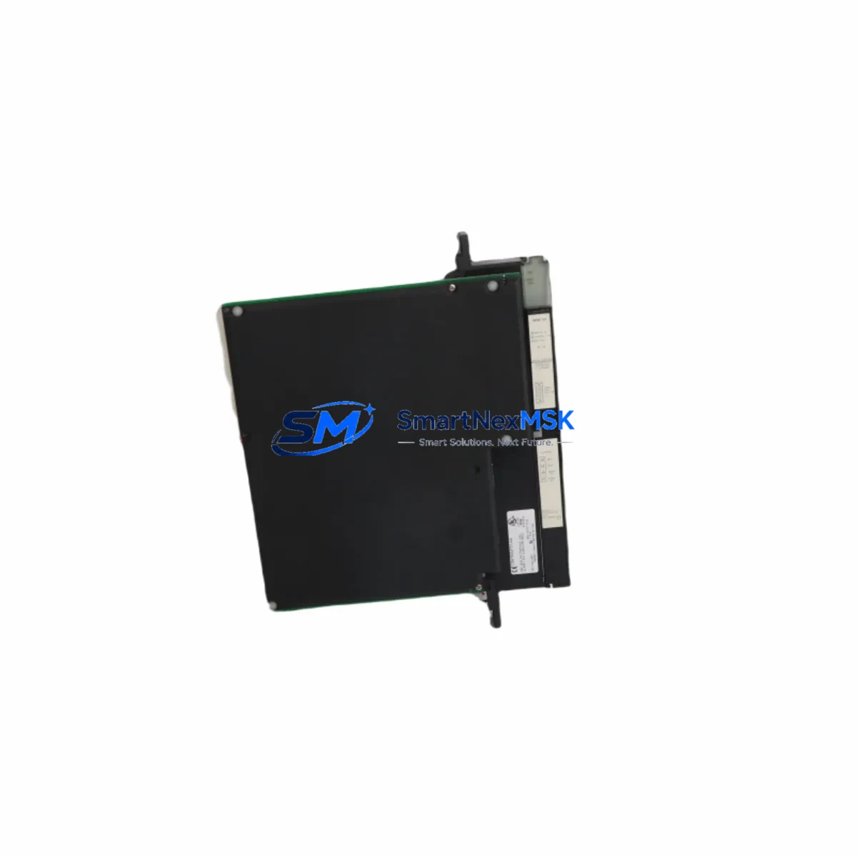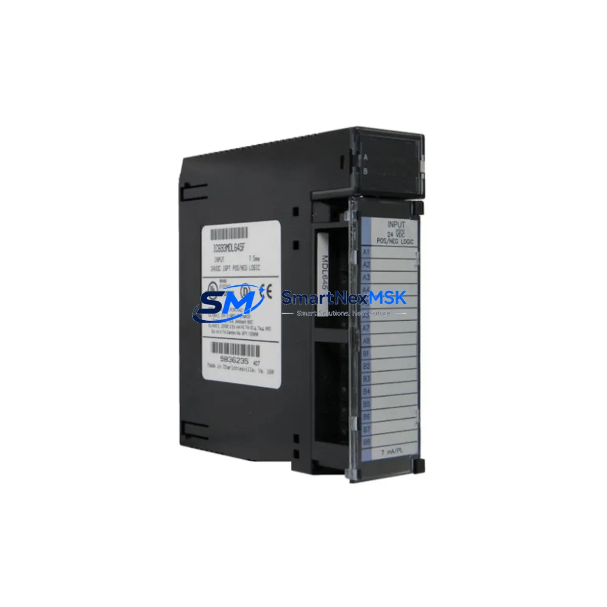
GE Fanuc IC693MDL645 Retrofit-Ready Discrete Input Module for Series 90-30 Control Systems
The GE Fanuc IC693MDL645 is a 24VDC, 16-point discrete input module engineered for the Series 90-30 programmable logic controller platform. As legacy Series 90-30 systems approach end-of-life and original spare parts become increasingly scarce, the IC693MDL645 remains one of the most sought-after retrofit-ready replacements for aging control cabinets across manufacturing, utilities, water treatment, and process automation industries. Whether you are executing a planned system upgrade, recovering from an unplanned failure, or building a strategic spare-parts inventory, this module delivers verified drop-in compatibility with the Series 90-30 backplane architecture and existing field wiring.
Upgrade Compatibility Table
| Parameter | IC693MDL645 Specification | Retrofit Notes |
|---|---|---|
| Input Voltage | 24VDC (Positive or Negative Logic) | Verify field supply voltage before installation; compatible with most 24VDC field devices |
| Input Points | 16 Points | Direct replacement for other 16-point 24VDC input modules in the Series 90-30 family |
| Backplane Interface | Series 90-30 Standard Backplane Connector | Compatible with IC693CHS391, IC693CHS392, IC693CHS393 racks; no adapter required |
| Module Slot Address | Configurable via Proficy Machine Edition / Logicmaster 90 | Retain original slot address in program to avoid I/O remapping; verify in hardware configuration |
| Communication Protocol | Local I/O Bus (Series 90-30 native) | No protocol migration required for local rack installations; compatible with IC693CMM321 and IC693CMM311 communication modules |
| Terminal Wiring | 40-pin removable terminal block | Existing field wiring can be transferred directly; label all terminals before removal |
| Power Consumption | Draws from backplane 5VDC bus | Verify IC693PWR321 or IC693PWR330 power supply capacity before adding modules to existing rack |
| HMI Compatibility | Compatible with iFIX, Cimplicity, and third-party SCADA via CPU data tables | No HMI screen changes required if I/O addresses are preserved |
| Replacement Candidates | IC693MDL640, IC693MDL641, IC693MDL643, IC693MDL644 | Confirm point count and voltage rating match before substituting |
| Warranty | 12-Month Warranty | Covers manufacturing defects; each unit ships after functional bench test |
Retrofit Planning for Existing Automation Systems
Successful integration of the IC693MDL645 into an existing Series 90-30 control system begins well before the module arrives on-site. A thorough retrofit plan addresses power budget, wiring continuity, program compatibility, and communication integrity across the entire control cabinet.
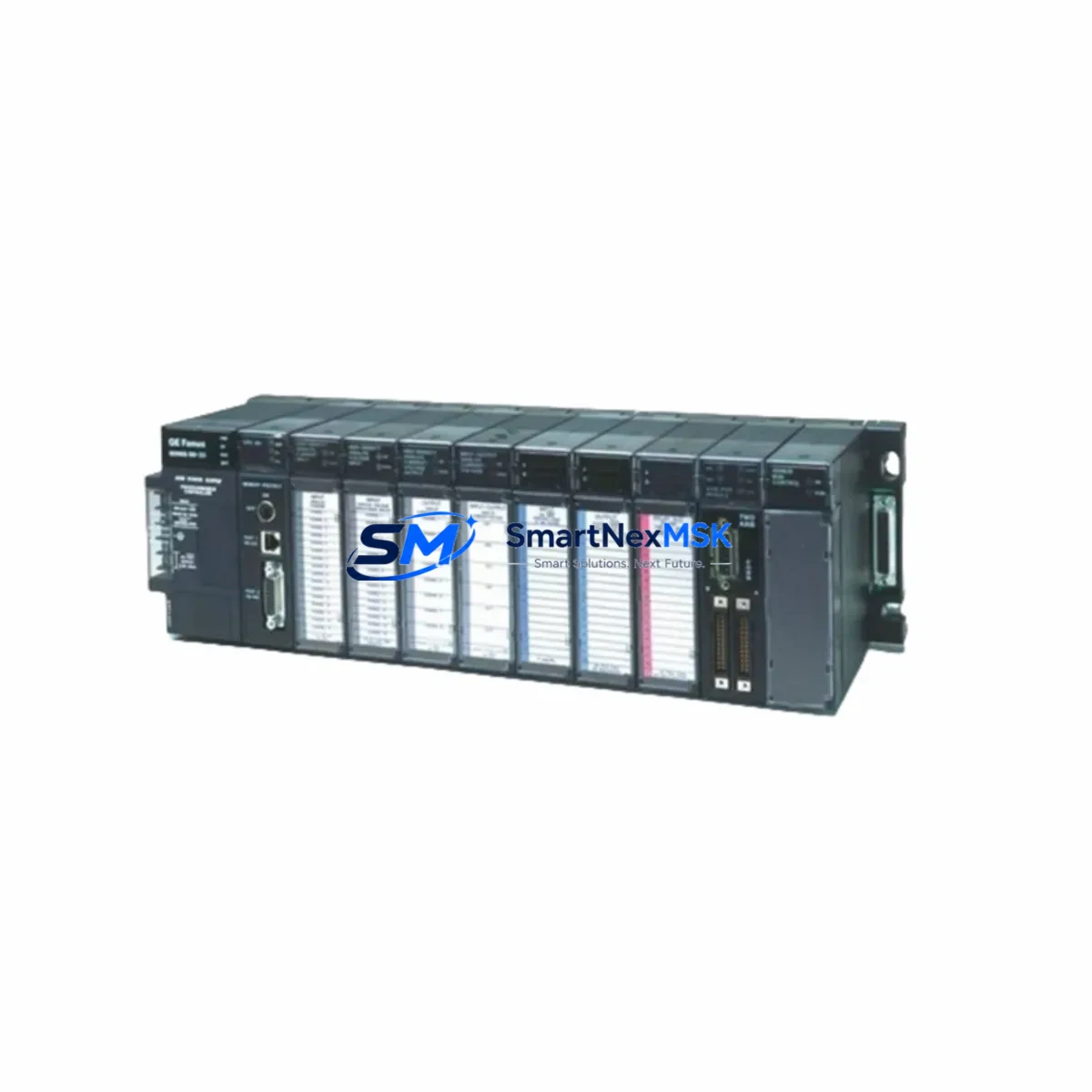
Start by auditing the rack configuration. The IC693MDL645 installs into any standard Series 90-30 rack, including the IC693CHS391 5-slot chassis, the IC693CHS392 10-slot chassis, and the IC693CHS393 10-slot chassis with expanded I/O capacity. Before inserting the replacement module, confirm that the installed IC693PWR321 or IC693PWR330 power supply has sufficient 5VDC bus capacity to support the full rack load. Adding or replacing modules without verifying power headroom is a common cause of intermittent faults and unexpected CPU resets.
Terminal wiring is the next critical checkpoint. The IC693MDL645 uses a 40-pin removable terminal block that accepts the same field wiring as predecessor modules such as the IC693MDL640 and IC693MDL641. Before disconnecting any wires, photograph and document every terminal connection. Label each conductor with its corresponding I/O address from the existing program. This documentation becomes essential during post-installation verification and any future maintenance events.
Program compatibility is typically straightforward when replacing a like-for-like module. Open the existing ladder logic in Proficy Machine Edition or the legacy Logicmaster 90 programming software and confirm that the hardware configuration reflects the correct module type in the target slot. If the replacement module is a different variant — for example, substituting an IC693MDL643 with the IC693MDL645 — review the input filter timing and logic polarity settings to ensure the program behavior remains consistent. No changes to the CPU itself, such as the IC693CPU374 or IC693CPU364, are required for a standard module swap.
For systems that use remote I/O expansion through a Genius Bus Controller such as the IC693BEM331, or that communicate over Ethernet using the IC693CMM321 Ethernet Interface Module, verify that the module address assignments in the hardware configuration table remain unchanged after the swap. Altering slot assignments without updating the program will cause I/O faults and may trigger safety interlocks in process-critical applications.
HMI screens connected via Cimplicity or iFIX reference CPU data table addresses, not physical module slots. As long as the I/O addresses are preserved in the program, no HMI screen modifications are necessary. This significantly reduces retrofit risk and keeps commissioning time to a minimum.
Finally, if the control system includes a programming cable such as the IC690ACC901 or a USB-to-serial adapter for legacy CPU connections, have it available on-site during commissioning. The ability to go online with the CPU immediately after module installation allows you to force inputs, verify scan cycle behavior, and confirm that all 16 input points are reading correctly before returning the system to production.
Downtime Control During System Migration
Minimizing unplanned downtime is the primary concern for any maintenance engineer executing a Series 90-30 module replacement. The IC693MDL645 is designed to support hot-swap-aware procedures that protect original program logic and maintain field control continuity throughout the migration process.
Before removing the failed or obsolete module, place the CPU in Stop mode using the keyswitch or through the programming software. This prevents the CPU from generating I/O fault alarms that could cascade into downstream equipment trips or safety system activations. If the system is running a continuous process where a hard stop is not acceptable, coordinate with the operations team to identify a safe window — even a 15-minute planned outage is far preferable to an uncontrolled failure during peak production.
Back up the current program to a PC or programming device before touching any hardware. Proficy Machine Edition allows you to upload the full program, including hardware configuration, data tables, and motion parameters, in a single operation. Store this backup in at least two locations. If the CPU is an older model such as the IC693CPU331 or IC693CPU341 that uses battery-backed RAM, verify that the backup battery is functional before proceeding. A battery failure during a module swap can result in complete program loss.
Once the IC693MDL645 is seated in the rack and the terminal block is reconnected, power the system and bring the CPU back online. Use the programming software to go online and monitor the input status table in real time. Force each of the 16 input points individually to confirm that field signals are being read correctly. Check the I/O fault table for any unresolved errors before returning the CPU to Run mode.
For facilities that maintain a hot standby or redundant CPU configuration, the IC693MDL645 supports the same redundancy architecture as the original module, allowing the standby CPU to take control seamlessly during the swap window. This approach reduces effective downtime to near zero for critical continuous-process applications.
Every IC693MDL645 unit shipped by SMARTNEXMSK undergoes a functional bench test prior to dispatch, verifying all 16 input channels, backplane communication, and LED indicator operation. This pre-shipment testing protocol is part of our commitment to reducing on-site commissioning risk and supporting your downtime control objectives.
Retrofit Support FAQ
Q1: Is the IC693MDL645 a direct drop-in replacement for the IC693MDL640 and IC693MDL641?
In most applications, yes. All three modules are 24VDC discrete input modules for the Series 90-30 platform and share the same backplane connector and terminal block pinout. The primary difference lies in input filter timing and logic polarity options. Review your existing hardware configuration in Proficy Machine Edition to confirm the module type setting and adjust if necessary. No changes to the CPU program logic are required if the slot address is preserved.
Q2: What wiring changes are needed when installing the IC693MDL645?
In a like-for-like replacement scenario, no wiring changes are required. The 40-pin removable terminal block transfers directly from the old module to the new one. Document all terminal connections before removal, and verify continuity on each input circuit after reinstallation. If you are migrating from a module with a different terminal block configuration, consult the IC693MDL645 hardware installation manual for the correct wiring diagram.
Q3: How do I verify compatibility with my existing Series 90-30 CPU and rack?
The IC693MDL645 is compatible with all Series 90-30 CPUs, including the IC693CPU331, IC693CPU341, IC693CPU351, IC693CPU360, IC693CPU363, IC693CPU364, and IC693CPU374, as well as all standard Series 90-30 rack configurations. Open your hardware configuration in Proficy Machine Edition or Logicmaster 90 and confirm that the target slot is configured for a 16-point 24VDC input module. If the slot was previously occupied by a different module type, update the hardware configuration and download it to the CPU before going to Run mode.
Q4: What does the 12-month warranty cover, and what is the shipping and testing process?
Every IC693MDL645 unit is functionally tested before shipment, covering all 16 input channels, backplane interface integrity, and LED indicator operation. The 12-month warranty covers manufacturing defects and functional failures under normal operating conditions. Units are shipped with anti-static packaging and include a test report on request. For urgent retrofit requirements, expedited shipping options are available. Contact our technical sales team at [email protected] or +86 18259474341 to confirm lead time and stock availability before placing your order.
© 2026 SMARTNEXMSK. All rights reserved.
Original Source: https://smartnexmsk.com
Contact: [email protected] | +86 18259474341