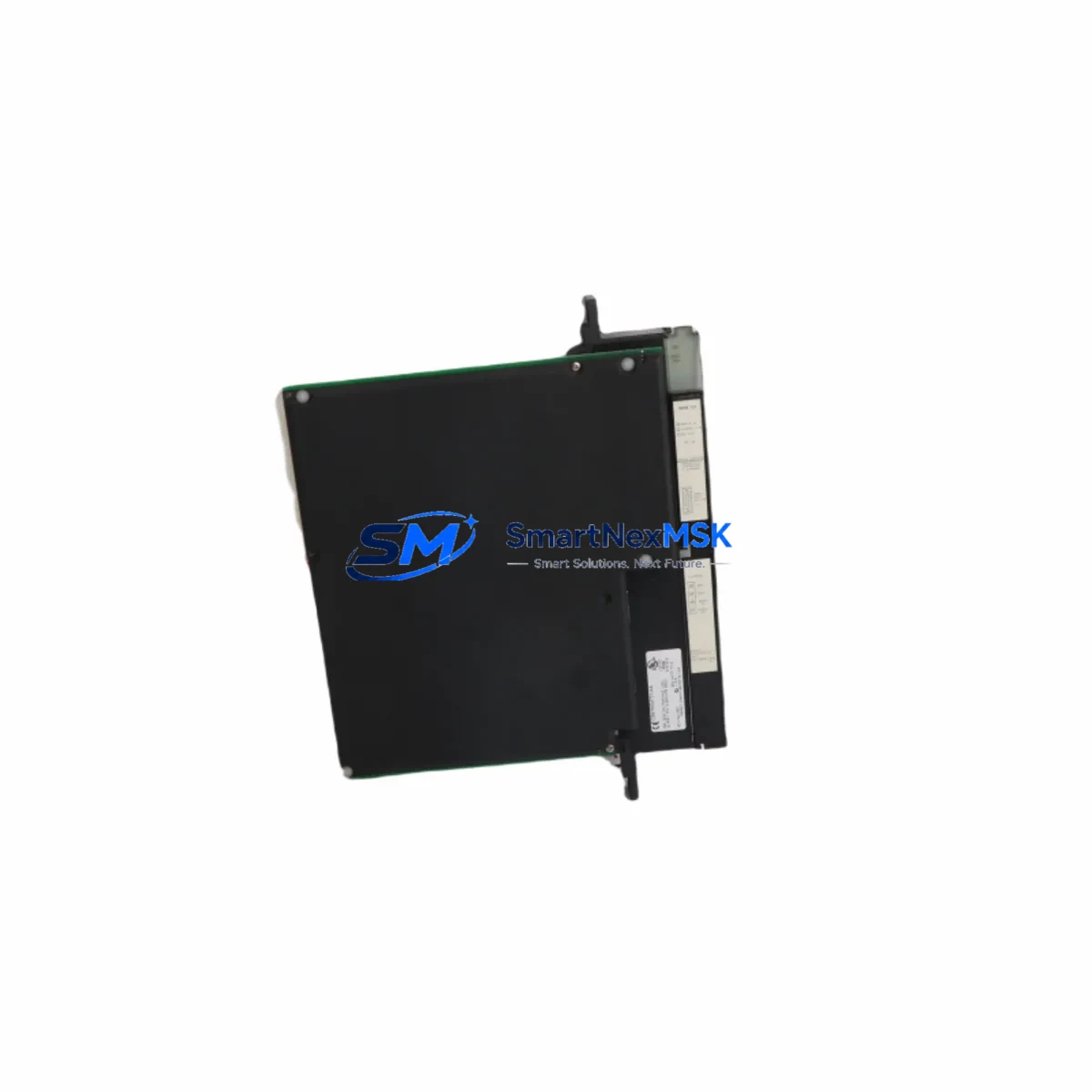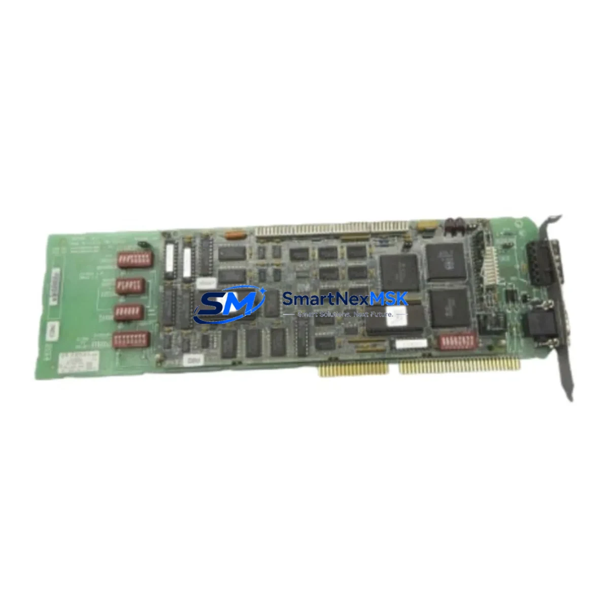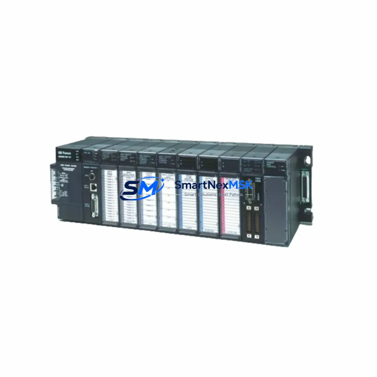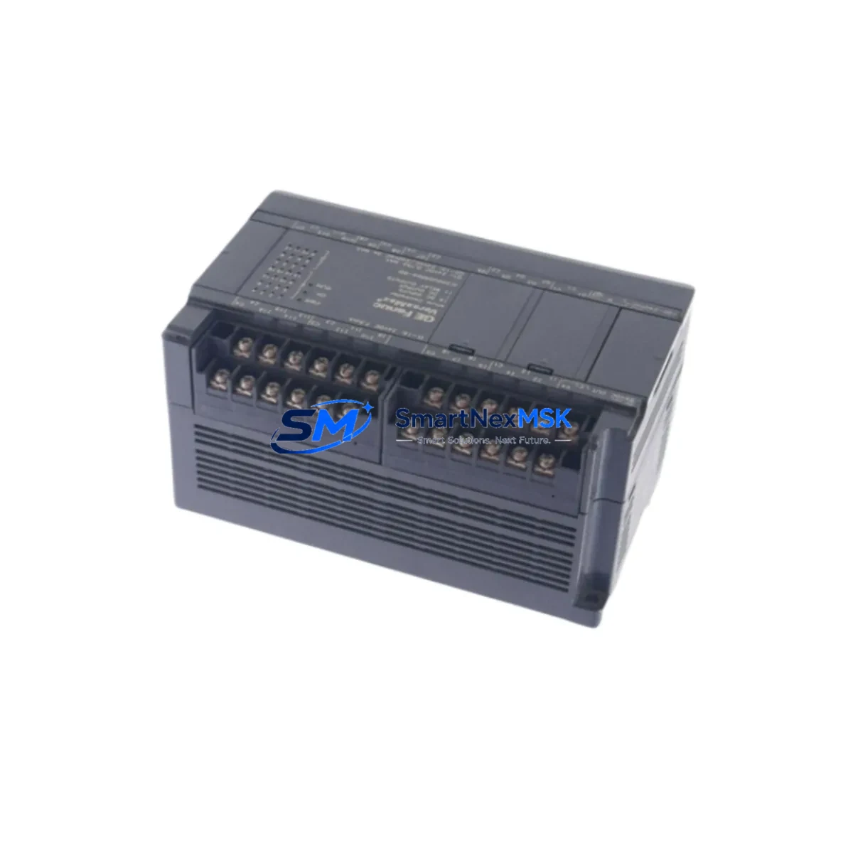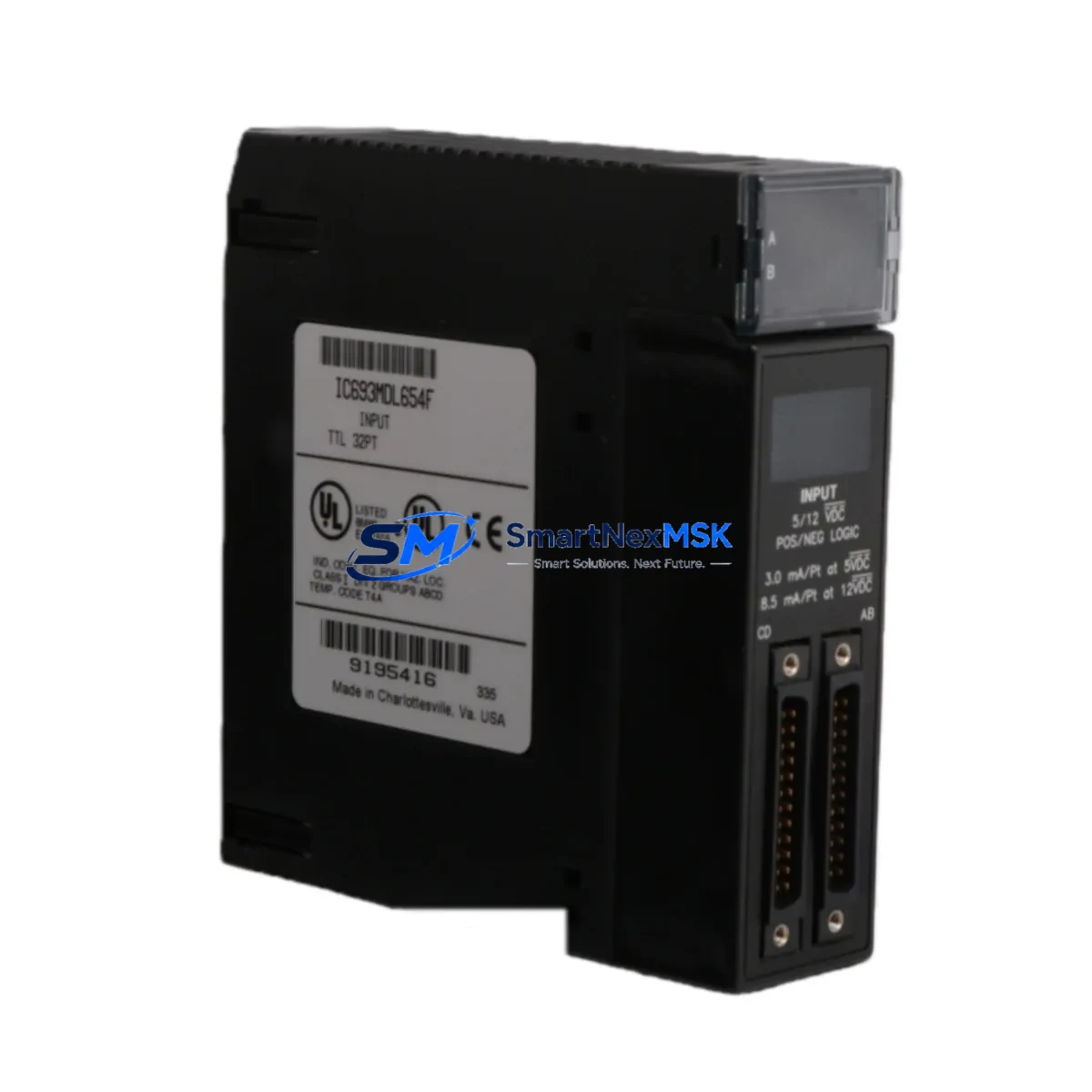
GE Fanuc IC693MDL654 Maintenance-Ready Spare for 90-30 Automation
The IC693MDL654 is a 32-point, 24VDC discrete input module designed for the GE Fanuc Series 90-30 programmable logic controller platform. As a critical field-replaceable unit in distributed control architectures, this module serves as the primary interface between field-level sensors, proximity switches, push-buttons, and the CPU backplane. Maintaining a verified spare of the IC693MDL654 in your parts inventory is a foundational practice for any facility operating Series 90-30 systems in continuous production, utilities, or process automation environments.
Each unit supplied by SMARTNEXMSK is sourced as an original GE Fanuc component, subjected to functional power-on verification and I/O channel continuity testing prior to dispatch. All units ship with a 12-month warranty covering manufacturing defects and operational failure under normal industrial service conditions.
Spare Maintenance Table
| Parameter | Specification |
|---|---|
| Part Number | IC693MDL654 |
| Brand / Manufacturer | GE Fanuc (GE Automation & Controls) |
| Compatible Series | Series 90-30 PLC (IC693 family) |
| Module Type | 32-Point Discrete Input Module |
| Input Voltage | 24VDC (Sink/Source) |
| Points per Module | 32 isolated input channels |
| Backplane Interface | Series 90-30 5-slot / 10-slot rack compatible |
| Input Signal Range | 0–30VDC; ON threshold ≥ 11VDC |
| Isolation | Optical isolation, field side to backplane |
| Operating Temperature | 0°C to 60°C (32°F to 140°F) |
| Relative Humidity | 5–95% non-condensing |
| Installation | DIN-rail rack mount, hot-swap capable with CPU in stop mode |
| Maintenance Recommendation | Inspect terminal wiring annually; verify LED status indicators during scheduled PM |
| Warranty | 12 Months — covers manufacturing defects and operational failure |
| Condition | Original, tested before shipment |
Maintenance Planning for Continuous Operation
When a Series 90-30 system experiences discrete input faults, the IC693MDL654 is rarely the sole component requiring attention. A disciplined maintenance engineer will treat module replacement as the trigger for a broader cabinet inspection. Begin by verifying the 24VDC field power supply — modules such as the IC693PWR321 or IC693PWR330 power supply units should be load-tested to confirm stable output voltage under full I/O load. Voltage sag or ripple at the field supply rail is a common root cause of intermittent input misreads that are incorrectly attributed to module failure.
Inspect the IC693CHS391 or IC693CHS397 rack chassis for backplane connector wear, bent pins, or oxidation on the module edge connectors. A degraded backplane connection can cause sporadic channel faults even when the IC693MDL654 itself is fully functional. While the rack is partially populated, this is also the appropriate time to inspect adjacent modules: the IC693MDL752 discrete output module sharing the same I/O group, and any IC693ALG221 or IC693ALG222 analog input modules in the same chassis, should be visually inspected for heat discoloration or terminal corrosion.
Terminal block wiring at the field connector should be re-torqued to manufacturer specification. Loose field wiring is the leading cause of nuisance input faults in high-vibration environments such as compressor stations, press lines, and conveyor systems. If the installation uses IC693ACC300 series terminal blocks or third-party marshalling panels, verify that all field cable shields are properly grounded at a single point to prevent common-mode noise from corrupting input states.
For facilities running legacy Series 90-30 CPUs such as the IC693CPU364 or IC693CPU374, confirm that the CPU firmware revision supports the full 32-channel addressing of the IC693MDL654 without requiring a configuration download after hot-swap. Document the slot address and I/O map reference in your CMMS before removing the faulty module to ensure the replacement is configured identically. Where a Profibus or Ethernet communications module such as the IC693CMM321 is installed in the same rack, verify that the network node remains online during the module swap to avoid triggering upstream SCADA alarms.
Site Replacement Workflow
Replacing the IC693MDL654 in a live Series 90-30 system follows a structured sequence to minimize unplanned downtime and avoid configuration errors. First, place the CPU in STOP mode via the programming terminal or the IC693CPU keyswitch — never remove a discrete input module with the CPU in RUN mode unless the system has been validated for hot-swap operation at that slot. Record the current I/O fault table from the programming software (Proficy Machine Edition or the legacy Logicmaster 90-30) before disconnecting field wiring.
Label and photograph all field wiring connections at the 40-pin connector before removal. Disconnect the field connector, release the module locking tab, and slide the IC693MDL654 out of the rack slot. Insert the replacement module, reconnect the field connector, and verify that all 32 LED input indicators respond correctly to known field signal states before returning the CPU to RUN mode. Perform a forced I/O test on at least four representative channels — one from each 8-point group — to confirm channel-to-channel isolation integrity.
For systems where the IC693MDL654 is replacing an older IC693MDL651 (16-point, 24VDC input) due to a consolidation or upgrade, update the hardware configuration in the programming software to reflect the new module type and re-download the I/O configuration block. Verify that the PLC program logic correctly addresses all 32 input points and that any unused channels are masked in the fault masking register to prevent nuisance fault generation.
SMARTNEXMSK maintains ongoing stock of the IC693MDL654 and related Series 90-30 components to support emergency procurement timelines. Standard lead time for in-stock units is 1–3 business days with express international shipping available. All units are individually packaged in anti-static ESD bags with foam cushioning to prevent transit damage to the backplane connector and terminal block interface.
Spare Parts Support FAQ
Q: Is the IC693MDL654 compatible with all Series 90-30 rack configurations?
A: Yes. The IC693MDL654 is compatible with all standard Series 90-30 5-slot (IC693CHS391) and 10-slot (IC693CHS397) rack chassis. It occupies a single slot and is addressed as a standard discrete input module in both Logicmaster 90-30 and Proficy Machine Edition programming environments. Confirm the slot address in your hardware configuration matches the physical installation before downloading.
Q: What is included in the 12-month warranty and how is a claim processed?
A: The 12-month warranty covers manufacturing defects and operational failure under normal industrial service conditions from the date of shipment. To initiate a warranty claim, contact [email protected] with the order reference, a description of the fault symptom, and the result of any diagnostic steps taken. SMARTNEXMSK will arrange return shipping and dispatch a replacement unit upon fault confirmation.
Q: How do I verify the IC693MDL654 is functioning correctly after installation?
A: After installation and CPU restart, use the I/O forcing function in Proficy Machine Edition or Logicmaster 90-30 to individually force each input channel and verify the corresponding LED indicator and PLC register bit respond correctly. Additionally, review the I/O fault table in the CPU diagnostics screen — a healthy module will show no active faults on any of the 32 channels under normal field wiring conditions.
Q: Can SMARTNEXMSK support long-term or blanket purchase orders for Series 90-30 spare parts?
A: Yes. SMARTNEXMSK supports blanket purchase orders and long-term supply agreements for facilities managing aging Series 90-30 infrastructure. We maintain buffer stock of high-demand modules including the IC693MDL654 and can provide scheduled delivery programs aligned with your annual maintenance budget cycle. Contact [email protected] to discuss volume pricing and supply continuity arrangements.
© 2026 SMARTNEXMSK. All rights reserved.
Original Source: https://smartnexmsk.com
Contact: [email protected] | +86 18259474341