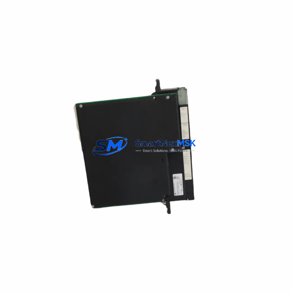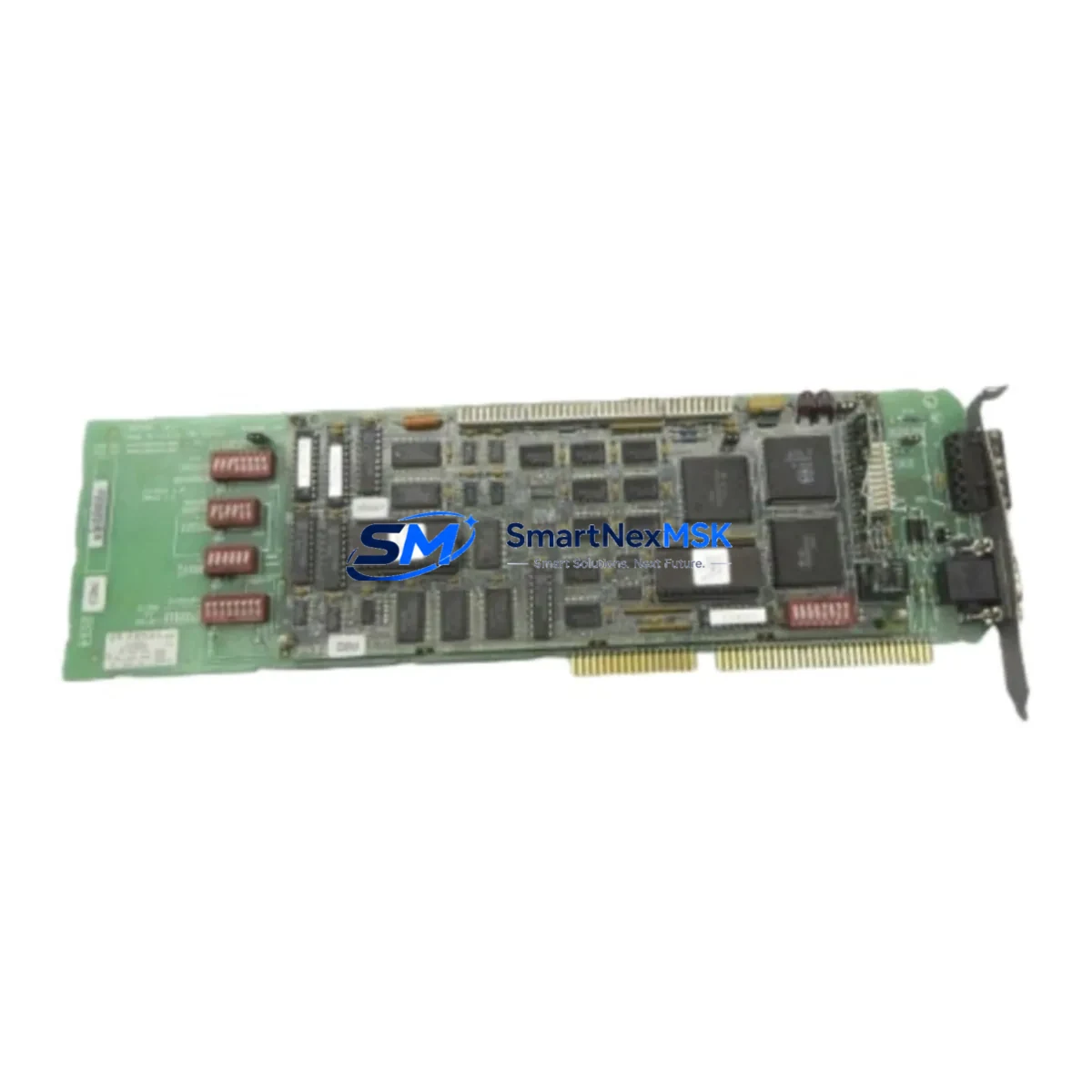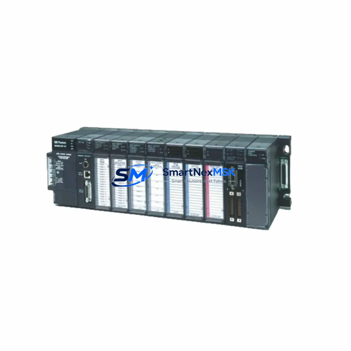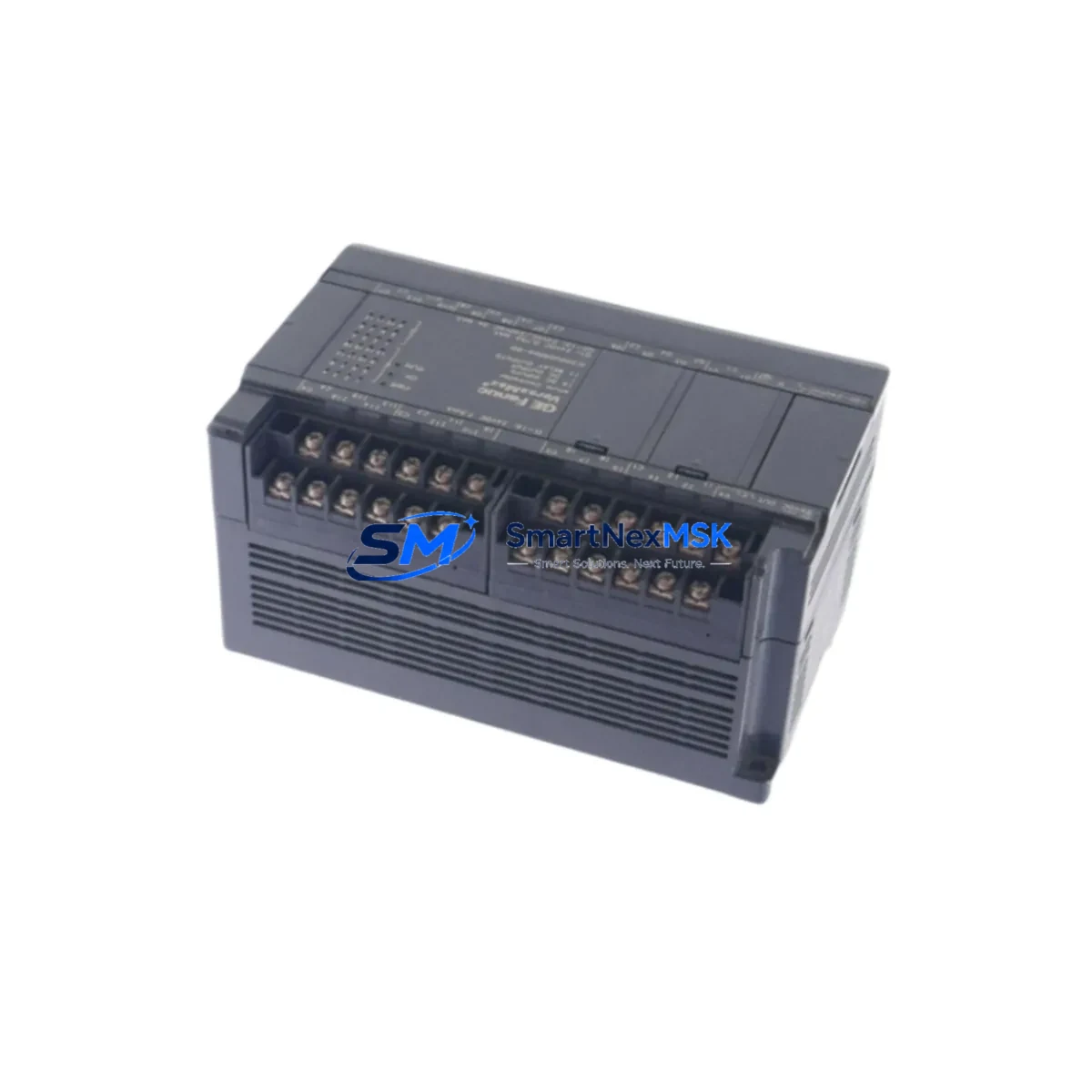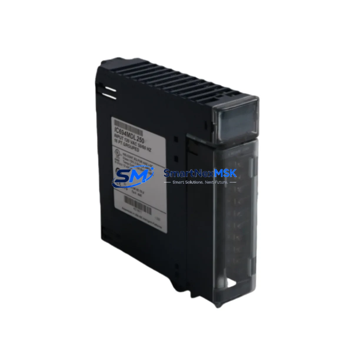
GE Fanuc IC694MDL250 Spare for Series 90-30 Automation
The GE Fanuc IC694MDL250 is a 16-point, 120VAC discrete input module engineered for the Series 90-30 PLC platform — one of the most widely deployed programmable logic controller families in North American industrial automation. For maintenance engineers managing aging control systems, sourcing a verified, original IC694MDL250 spare is critical to minimizing unplanned downtime and restoring production continuity. This module is supplied as a tested, original spare, ready for immediate installation, and backed by a 12-month warranty.
Whether you are executing a planned shutdown inspection, responding to an emergency I/O fault, or building a strategic spare parts inventory for a Series 90-30 rack, the IC694MDL250 represents a direct, drop-in replacement that preserves full system compatibility without requiring software reconfiguration or hardware adaptation.
Spare Maintenance Table
| Parameter | Specification |
|---|---|
| Part Number | IC694MDL250 |
| Brand | GE Fanuc (now Emerson / Proficy) |
| Series | Series 90-30 |
| Module Type | Discrete Input Module |
| Input Points | 16 Points |
| Input Voltage | 120VAC |
| Input Current (per point) | ~10 mA @ 120VAC |
| Isolation | Optical isolation, group isolated |
| Backplane Compatibility | IC693CHS391, IC694CHS392, IC694CHS398 and compatible Series 90-30 racks |
| Operating Temperature | 0°C to 60°C (32°F to 140°F) |
| Relative Humidity | 5% to 95% non-condensing |
| Installation | DIN rail / panel mount via Series 90-30 rack |
| Maintenance Recommendation | Inspect terminal wiring, verify LED status indicators, confirm backplane seating annually |
| Condition | Original, tested before shipment |
| Warranty | 12 Months |
Maintenance Planning for Continuous Operation
When replacing the IC694MDL250 in a Series 90-30 control cabinet, a thorough maintenance engineer will treat the module swap as an opportunity to audit the surrounding electrical environment. The 120VAC input wiring should be inspected for insulation degradation, loose terminal connections, and correct fusing — typically through dedicated fuse blocks or terminal-mounted fuse holders rated for the input voltage group.
The IC694MDL250 shares its rack with other Series 90-30 modules that should be evaluated during the same maintenance window. The CPU module — commonly an IC693CPU374 or IC694CPU310 — should be checked for battery backup status and firmware revision. The power supply module, such as the IC693PWR321 or IC694PWR330, should be load-tested to confirm it is delivering stable 5VDC backplane power, as a marginal power supply is a frequent root cause of intermittent I/O faults that are misdiagnosed as module failures.
Discrete output modules installed in adjacent slots — for example the IC694MDL340 (16-point 120VAC output) or IC694MDL754 (32-point 24VDC output) — should have their output wiring and load circuits verified. Relay output modules such as the IC694MDL930 are particularly susceptible to contact wear in high-cycle applications and are a recommended co-inspection item. Communications modules, including the IC694CMM321 Ethernet interface or IC693CMM311 serial module, should have their network connections and status LEDs confirmed during any planned rack-level maintenance.
For systems using analog I/O alongside discrete inputs, the IC694ALG220 or IC694ALG232 analog input modules in the same rack should be calibrated and their signal wiring checked for shielding continuity. Signal isolators installed between field devices and the PLC input terminals are a critical protection layer — any 4-20mA or voltage signal isolator showing drift should be replaced proactively. Terminal blocks and wiring duct within the control cabinet should be inspected for heat discoloration, which can indicate sustained overload conditions upstream of the IC694MDL250 input circuits.
Building a minimum viable spare parts kit around the IC694MDL250 for a Series 90-30 installation should include at least one CPU battery, one power supply module, one discrete input module, one discrete output module, and the relevant communications module for the network topology in use. This approach supports a rapid recovery posture and reduces mean time to repair (MTTR) to under one hour for most common fault scenarios.
Site Replacement Workflow
Step 1 — Fault Isolation: Confirm the fault is isolated to the IC694MDL250 by reviewing the PLC fault table in the programming software (Proficy Machine Edition or Logicmaster 90). Check for I/O fault codes referencing the specific rack slot occupied by the module.
Step 2 — Safe De-energization: Isolate the 120VAC field wiring at the upstream fuse or circuit breaker. Do not remove the module under live voltage. Verify isolation with a calibrated voltage tester before proceeding.
Step 3 — Module Removal: Release the module locking tab, disconnect the field wiring terminal block (if removable), and slide the module out of the backplane slot. Note the slot address for re-insertion.
Step 4 — Spare Installation: Insert the IC694MDL250 replacement into the same slot. The Series 90-30 backplane supports hot-insertion on some CPU revisions — confirm your CPU firmware supports this before attempting. Reconnect the field wiring terminal block and restore 120VAC supply.
Step 5 — Functional Verification: Power the rack and confirm the module’s LED indicators show normal status. Force individual input points from the programming terminal to verify all 16 channels are responding correctly before returning the system to automatic operation.
Step 6 — Documentation: Record the replacement in the site maintenance log, including the date, replaced module serial number, and technician name. Update the spare parts inventory to trigger reorder of a replacement spare.
Spare Parts Support FAQ
Q: Is the IC694MDL250 a direct replacement for the IC693MDL241 or IC693MDL250?
A: The IC694MDL250 is the Series 90-30 generation module and is functionally compatible with IC693-series racks in most configurations. However, always verify the rack model and backplane connector type before installation, as some early IC693 racks use a different backplane interface. Contact our technical team with your rack model for confirmation.
Q: What testing is performed before shipment?
A: Each IC694MDL250 unit is powered and functionally tested prior to shipment. Input channel continuity, optical isolation integrity, and backplane communication are verified. A test report is available upon request for critical infrastructure applications.
Q: How should I manage IC694MDL250 inventory for a multi-line facility?
A: For facilities running three or more Series 90-30 racks, we recommend maintaining a minimum of two IC694MDL250 spares on-site. High-cycle applications with frequent field device switching should increase this to three units. Spares should be stored in anti-static packaging in a climate-controlled environment and rotated into service on a first-in, first-out basis.
Q: What is covered under the 12-month warranty?
A: The 12-month warranty covers manufacturing defects and functional failures under normal operating conditions. It does not cover damage resulting from incorrect installation voltage, physical impact, or operation outside the specified temperature and humidity range. Warranty claims are processed with a replacement unit dispatched within 3 business days of fault confirmation.
© 2026 SMARTNEXMSK. All rights reserved.
Original Source: https://smartnexmsk.com
Contact: [email protected] | +86 18259474341