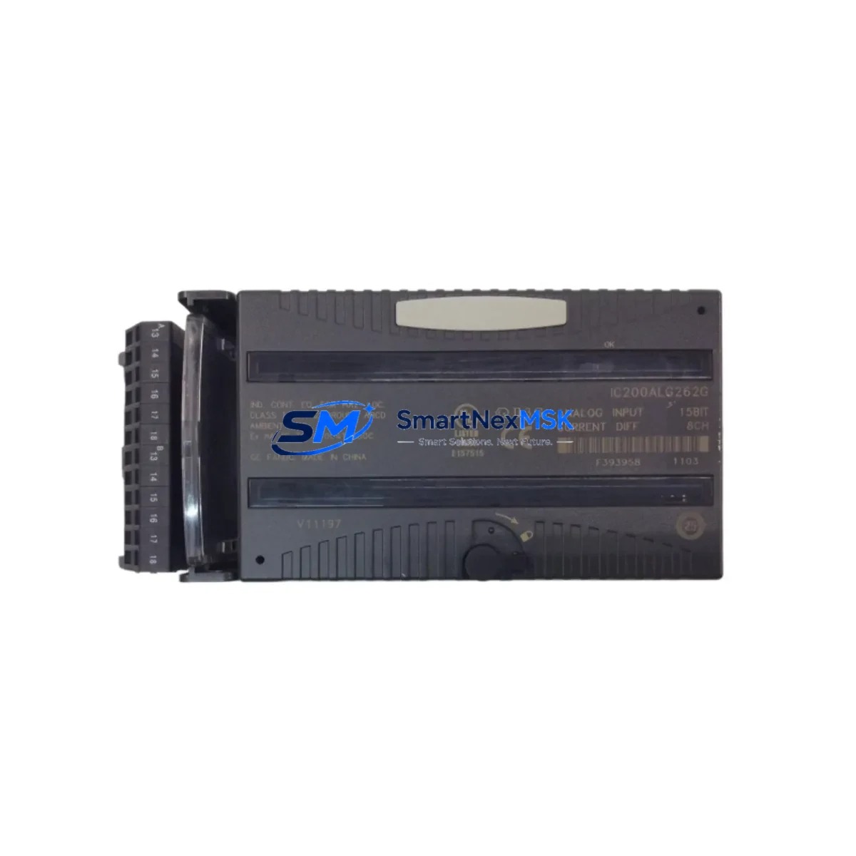
GE IC200ALG262G Maintenance-Ready Spare for VersaMax Automation
The GE IC200ALG262G is a 16-channel analog input module designed for the GE VersaMax distributed I/O platform. Rated for 0–20 mA current-loop inputs with 12-bit resolution, this module is a critical component in process control, machine automation, and continuous monitoring applications across manufacturing, utilities, and heavy industry. Maintaining a verified spare of the IC200ALG262G in your parts inventory is one of the most effective strategies for minimizing unplanned downtime and protecting production continuity in aging VersaMax-based control systems.
For maintenance engineers managing VersaMax control cabinets, the IC200ALG262G typically interfaces with field transmitters measuring pressure, flow, temperature, and level. When this module fails or degrades — often presenting as erratic analog readings, channel dropouts, or complete loss of input data — rapid replacement is essential. Each unit shipped by SMARTNEXMSK is tested prior to dispatch and backed by a 12-month warranty, ensuring you receive a field-ready spare that meets original GE specifications.
Spare Maintenance Table
| Parameter | Specification |
|---|---|
| Part Number | IC200ALG262G |
| Brand / Manufacturer | GE (General Electric) / Emerson |
| Series | VersaMax Distributed I/O |
| Module Type | Analog Input Module |
| Number of Channels | 16 Channels |
| Input Signal Range | 0–20 mA (current loop) |
| Resolution | 12-bit |
| Backplane Compatibility | VersaMax I/O Carrier / Backplane |
| Communication Interface | VersaMax Local Bus |
| Operating Temperature | 0°C to 60°C |
| Power Supply Requirement | Via VersaMax backplane (5 VDC logic) |
| Mounting | DIN rail / VersaMax carrier module |
| Origin | USA |
| Condition | Original, tested before shipment |
| Compatibility | GE VersaMax NIU, CPU001, CPU002, CPU005 systems |
| Maintenance Recommendation | Inspect wiring terminals, verify 4–20 mA loop integrity, confirm backplane seating annually |
| Warranty | 12 Months |
Maintenance Planning for Continuous Operation
When a VersaMax control cabinet requires inspection or the IC200ALG262G is flagged for replacement during a planned shutdown, experienced maintenance engineers know that the analog input module rarely fails in isolation. A thorough site inspection should extend to the surrounding electrical environment to prevent repeat failures and ensure system stability after the module swap.
Begin by verifying the IC200PWR001 or IC200PWR002 VersaMax power supply module — an under-voltage or ripple condition on the backplane 5 VDC rail is a common root cause of analog module instability. Next, inspect the IC200CHS002 or IC200CHS022 carrier/backplane assembly for corrosion, bent connector pins, or cracked housing that could cause intermittent contact with the IC200ALG262G.
Field wiring connected to the 16 analog input channels should be checked for insulation integrity, proper shielding, and correct termination at the terminal block or marshalling panel. In 4–20 mA loop-powered transmitter circuits, also verify the loop power supply and any signal isolators or loop-powered signal conditioners in the circuit — a failed isolator can mimic an analog module fault and lead to misdiagnosis.
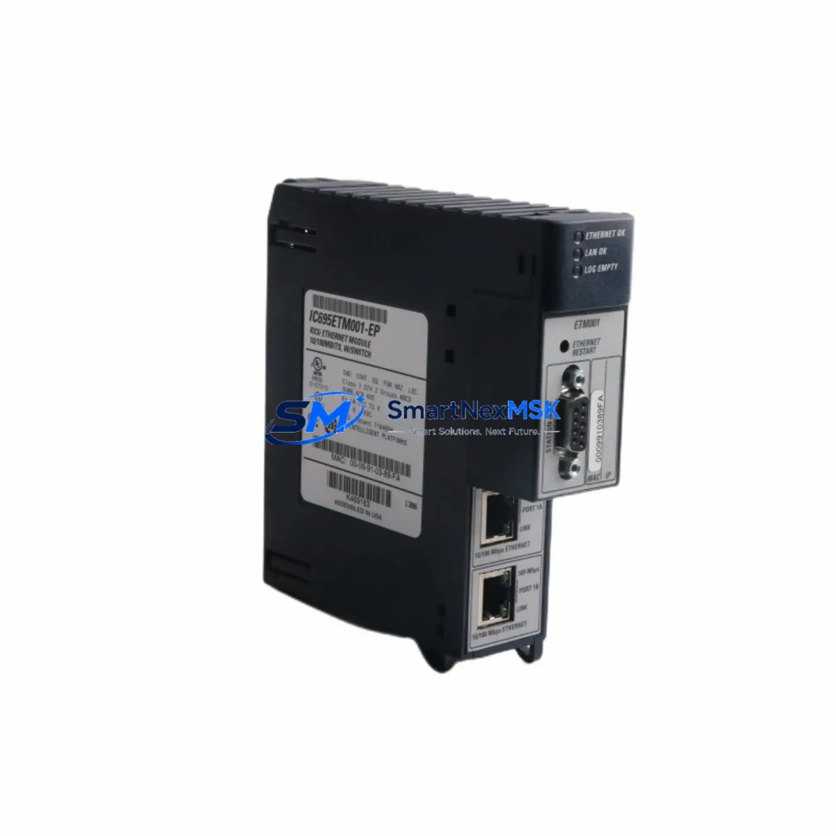
If the VersaMax system communicates over Ethernet or serial networks, inspect the IC200PBI001 PROFIBUS interface module or IC200ETM001 Ethernet TCP/IP module for firmware version compatibility after the analog module replacement, particularly if the system has been running legacy firmware. Communication module faults can cause the CPU to misread analog data even after a successful hardware swap.
For systems using the IC200CPU001 or IC200CPU005 VersaMax CPU module, confirm that the I/O configuration table in the PLC program correctly maps the replacement IC200ALG262G to the expected slot address. A slot address mismatch will result in the CPU reporting the module as faulted even when the hardware is fully functional. Also review any IC200MDL740 or IC200MDL741 discrete output modules in the same cabinet that may be interacting with analog-controlled actuators — verifying their output status during commissioning prevents cascading faults.
Finally, if the control system includes an HMI panel or operator workstation displaying analog trends, confirm that the tag database and scaling parameters are updated to reflect the replacement module’s channel assignments. Stale HMI configurations are a frequent source of post-maintenance alarms that delay return-to-service.
Site Replacement Workflow
Step 1 — Pre-replacement verification: Confirm the failed module’s slot position and record the current analog readings from the HMI or SCADA system. Download a backup of the PLC program and I/O configuration before any hardware changes.
Step 2 — Safe isolation: De-energize the VersaMax backplane segment containing the IC200ALG262G following your site’s lockout/tagout (LOTO) procedure. Disconnect field wiring from the module’s terminal block, labeling each wire by channel number to ensure correct reconnection.
Step 3 — Module removal and inspection: Remove the IC200ALG262G from the carrier. Inspect the backplane connector for damage. Clean the slot with compressed air if contamination is present.
Step 4 — Replacement installation: Seat the new IC200ALG262G firmly into the carrier until the locking tab engages. Reconnect field wiring per the original channel labeling. Restore power to the backplane.
Step 5 — Commissioning and verification: Power up the system and confirm the CPU recognizes the module without faults. Verify live analog readings on all 16 channels against known reference values from field transmitters. Check HMI displays for correct scaling and alarm thresholds.
Step 6 — Documentation: Record the replacement date, new module serial number, and post-commissioning readings in your maintenance log. Update your spare parts inventory to reorder a replacement IC200ALG262G for future use.
This workflow supports rapid return-to-service, typically achievable within 30–60 minutes for a prepared maintenance team with a pre-tested spare on hand.
Spare Parts Support FAQ
Q1: Is the IC200ALG262G compatible with all VersaMax backplane configurations?
The IC200ALG262G is compatible with standard VersaMax I/O carriers and backplanes used with GE VersaMax NIU, CPU001, CPU002, and CPU005 systems. Always verify the slot count and carrier type (local vs. remote) against your system’s hardware configuration manual before installation. If your system uses an older revision carrier, contact us to confirm hardware revision compatibility.
Q2: How is each unit tested before shipment?
Every IC200ALG262G unit shipped by SMARTNEXMSK undergoes functional verification prior to dispatch, including power-on self-test confirmation and visual inspection of connector integrity. Units are packaged in anti-static protective packaging to prevent ESD damage during transit. A 12-month warranty covers any defects in materials or workmanship from the date of receipt.
Q3: Can this module replace earlier revisions such as IC200ALG262 or IC200ALG262E?
The IC200ALG262G is the current production revision and is generally backward-compatible with earlier revisions (IC200ALG262, IC200ALG262E, IC200ALG262F) in the same carrier slot. However, minor firmware or hardware revision differences may affect behavior in specific system configurations. We recommend verifying compatibility with your GE VersaMax system documentation or contacting our technical team before substituting revisions in safety-critical applications.
Q4: What is your lead time and long-term supply availability for the IC200ALG262G?
SMARTNEXMSK maintains stock of the IC200ALG262G to support both emergency replacement and planned maintenance programs. Standard orders ship within 1–3 business days. For customers managing aging VersaMax systems, we recommend establishing a standing spare parts agreement to ensure long-term supply continuity as GE VersaMax components approach end-of-life status. Contact our team to discuss volume pricing and reserved inventory arrangements.
© 2026 SMARTNEXMSK. All rights reserved.
Original Source: https://smartnexmsk.com
Contact: [email protected] | +86 18259474341