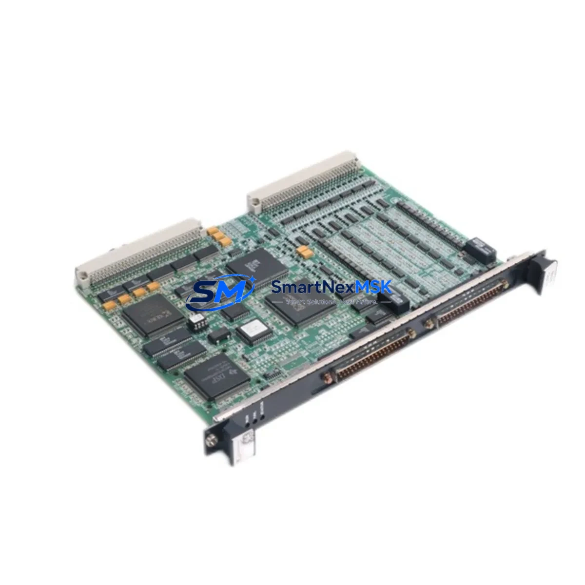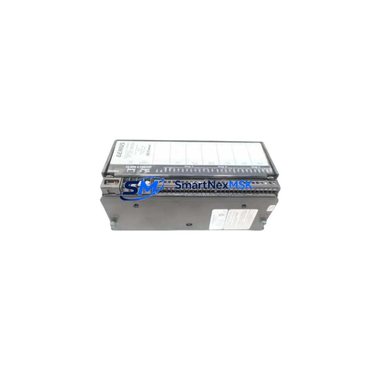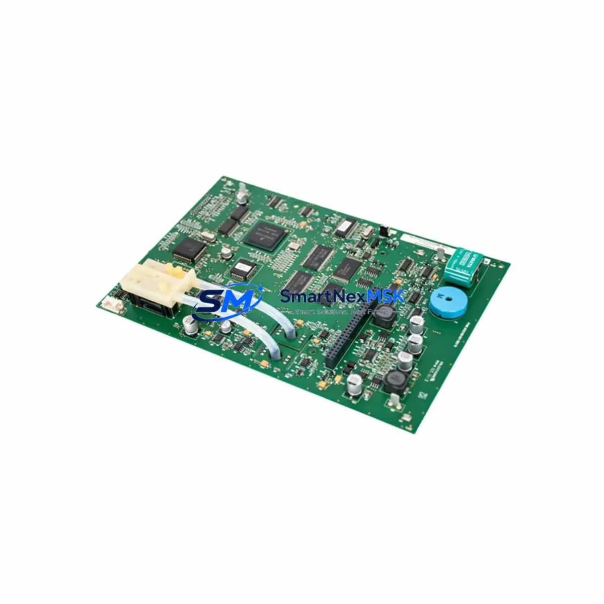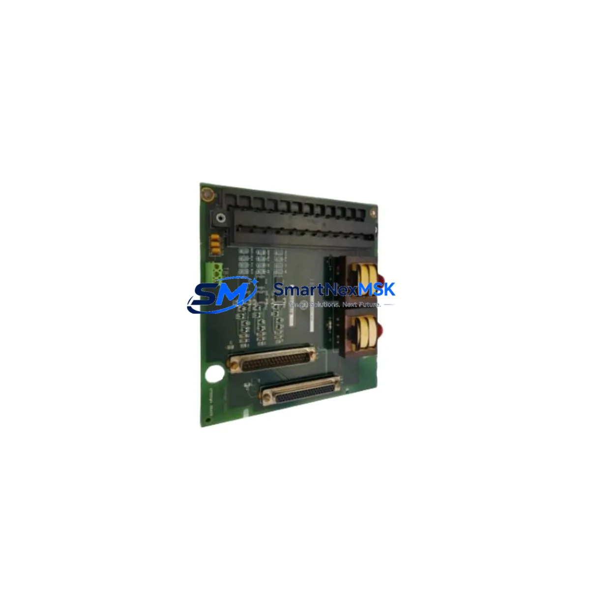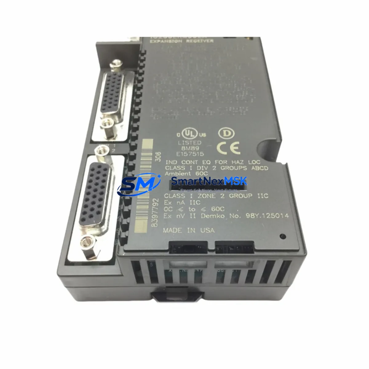
GE IC200ERM002 Retrofit-Ready I/O Expansion for VersaMax Control Systems
The GE IC200ERM002 is a VersaMax I/O Expansion Receiver Module engineered for distributed I/O architectures built on the GE VersaMax platform. As legacy VersaMax systems approach end-of-life and spare parts become increasingly scarce, the IC200ERM002 serves as a critical retrofit component for engineers tasked with modernizing aging control cabinets, extending operational life of existing automation lines, and migrating I/O infrastructure without full PLC replacement. Whether you are replacing a failed unit on a running production line or planning a phased upgrade of a multi-drop Genius bus network, the IC200ERM002 provides a reliable, specification-matched solution backed by a 12-month warranty and verified pre-shipment testing.
The IC200ERM002 functions as the receiver end of a VersaMax remote I/O drop, communicating with the host controller — typically a GE Series 90-30 CPU or a VersaMax Network Interface Unit such as the IC200BEM003 — over the Genius bus serial protocol. In retrofit scenarios, engineers must confirm that the existing Genius bus cable topology, termination resistors, and bus address settings on the replacement module match the original configuration precisely. The module occupies a standard VersaMax carrier, and its backplane interface is compatible with the IC200CHS series of I/O carriers, allowing direct substitution without mechanical modification to the control cabinet.
Before installation, technicians should verify the power supply capacity available at the remote drop. The IC200ERM002 draws logic power from the local VersaMax power supply — commonly the IC200PWR002 or IC200PWR102 — and any mismatch in power budget between the original and replacement configuration can cause intermittent faults or module lockout. It is strongly recommended to audit the total I/O load on the carrier, including any analog input modules such as the IC200ALG230 or discrete output modules such as the IC200MDL740, to ensure the power supply rating is not exceeded after the retrofit.
Terminal wiring compatibility is another key checkpoint during replacement. The IC200ERM002 does not include field wiring terminals directly; I/O signals are wired to the individual I/O modules seated on the carrier. When swapping a failed receiver module, field wiring to the I/O modules typically remains undisturbed, significantly reducing downtime. However, if the carrier itself — such as the IC200CHS022 — is also being replaced, technicians must document all terminal assignments before removal and verify continuity after reconnection.
Module address configuration on the IC200ERM002 is set via rotary switches on the module face. In a Genius bus network, each drop must carry a unique address. During retrofit planning, the existing address map should be extracted from the host PLC program — typically a GE Proficy Machine Edition project — and the replacement module must be configured to match the original address before power-up. Failure to match the address will cause the host CPU to report a loss-of-communication fault and may trigger a controlled shutdown of the affected I/O drop.
For sites migrating from older GE Series 90-30 architectures to a VersaMax-based distributed I/O strategy, the IC200ERM002 is frequently deployed alongside the IC200BEM003 Bus Expansion Module to extend the I/O network across larger physical distances within a facility. In these migration projects, the Genius bus wiring infrastructure is often reused, and the IC200ERM002 can be integrated into the new topology with minimal rewiring, provided bus loading calculations are reviewed and termination is correctly applied at both ends of the bus segment.
HMI screen updates are an often-overlooked element of a VersaMax retrofit. When I/O addresses change — even subtly — due to module resequencing or carrier reconfiguration, HMI tag bindings in platforms such as GE iFIX or Cimplicity must be audited and updated to reflect the new I/O map. Coordinating the PLC program download with the HMI tag update in a single maintenance window minimizes the risk of operator screen mismatches during the transition period.
Communication link integrity should be validated after installation using the Genius bus diagnostic tools available in Proficy Machine Edition. A successful retrofit is confirmed when the host CPU reports the remote drop as online, all I/O modules on the carrier are recognized, and forced I/O tests confirm correct signal routing from field devices through the IC200ERM002 to the control program. Pre-shipment testing of each IC200ERM002 unit at our facility includes power-on verification, bus communication handshake confirmation, and visual inspection of all connectors and backplane contacts.
Upgrade Compatibility Table
| Parameter | IC200ERM002 Specification | Retrofit Notes |
|---|---|---|
| Communication Protocol | Genius Bus (Serial, 153.6 kbps) | Compatible with existing Genius bus wiring; verify termination resistors at both ends |
| Backplane Interface | VersaMax I/O Carrier (IC200CHS series) | Direct drop-in on IC200CHS022 and compatible carriers; no mechanical modification required |
| Power Requirement | Supplied by local VersaMax power supply | Verify IC200PWR002 / IC200PWR102 capacity covers full I/O load on carrier |
| Module Address | Rotary switch, 0–31 | Must match original Genius bus drop address; extract from existing PLC program before removal |
| Installation Format | VersaMax modular, DIN-rail or panel mount | Same form factor as original; no cabinet modification needed |
| Host Controller Compatibility | GE Series 90-30, VersaMax CPU, IC200BEM003 | Confirm Proficy Machine Edition hardware configuration matches replacement module |
| Commissioning Tool | GE Proficy Machine Edition | Use Genius bus diagnostics to verify drop online status post-installation |
| Warranty | 12 Months | Covers manufacturing defects; includes pre-shipment power-on and communication test |
Retrofit Planning for Existing Automation Systems
A successful IC200ERM002 retrofit begins with a thorough audit of the existing VersaMax I/O network. Start by documenting the Genius bus topology: the number of drops, the address assigned to each IC200ERM002 or IC200ESM002 expansion sender module, and the physical routing of the bus cable. Next, inventory all I/O modules currently seated on the carrier — discrete input modules such as the IC200MDL640, discrete output modules such as the IC200MDL740, and any analog modules such as the IC200ALG230 or IC200ALG320 — and confirm that the replacement carrier and power supply can support the same I/O complement.
The local power supply is a frequent bottleneck in retrofit projects. The IC200PWR002 provides 30W of backplane power, while the IC200PWR102 offers 40W. If the original installation was running close to the power budget, adding a higher-capacity power supply during the retrofit is a low-cost insurance measure that prevents nuisance faults after the new IC200ERM002 is commissioned. Similarly, if the control cabinet includes a GE IC200BEM003 Bus Expansion Module extending the Genius bus to a second carrier, the power budget for that secondary carrier must be independently verified.
For sites that also operate GE Series 90-30 CPUs in the same control architecture, the retrofit plan should include a review of the CPU’s I/O configuration table in Proficy Machine Edition to confirm that the IC200ERM002 replacement is recognized under the same hardware slot assignment. If the original module was configured with a specific I/O map, any deviation in the replacement — such as a different firmware revision affecting data block layout — should be identified and addressed in the PLC program before the replacement module is powered on in the live system.
Programming cables such as the IC690ACC901 serial programming cable or a USB-to-serial adapter configured for the SNP protocol are essential tools during commissioning. Having the programming cable connected and Proficy Machine Edition running in online monitoring mode during the first power-up of the replacement IC200ERM002 allows the technician to observe the Genius bus status in real time and immediately identify any address conflicts or wiring faults before they escalate into production stoppages.
Downtime Control During System Migration
Minimizing downtime during an IC200ERM002 replacement requires preparation before the maintenance window opens. The replacement module should be pre-configured — bus address set, firmware version confirmed, and physical connectors inspected — so that the actual swap can be completed in minutes rather than hours. A pre-written commissioning checklist covering power isolation, module removal, replacement installation, address verification, power restoration, and Genius bus diagnostic confirmation ensures that no step is missed under time pressure.
Where the production process permits, a hot-standby approach can be used: the replacement IC200ERM002 is staged in a test rack with a spare IC200PWR002 power supply and a representative set of I/O modules, and the Genius bus communication is verified offline before the live swap. This approach is particularly valuable in continuous-process industries where even a 15-minute unplanned outage carries significant cost.
Protecting the original PLC program logic is non-negotiable. Before any hardware change, the current program should be uploaded from the host CPU and saved to a secure backup location. If the retrofit involves any changes to the I/O configuration table in Proficy Machine Edition — for example, to accommodate a different module revision — the modified program should be compiled, verified in simulation mode, and reviewed by the responsible engineer before being downloaded to the live CPU. This discipline ensures that the control logic governing the production process remains intact and that the retrofit does not inadvertently alter any safety interlocks or process setpoints.
Field control continuity during the migration window can be maintained by placing the affected I/O drop in a forced-output state for non-critical outputs, allowing the process to continue in a degraded-but-safe mode while the IC200ERM002 is being replaced. Once the replacement module is online and the Genius bus diagnostic confirms normal communication, forced outputs should be released in a controlled sequence and process variables monitored for stability before returning the line to full automatic control.
Retrofit Support FAQ
Q: Is the IC200ERM002 a direct drop-in replacement for a failed VersaMax expansion receiver?
A: Yes. The IC200ERM002 is specification-matched to the original GE VersaMax Expansion Receiver Module. It installs on the same IC200CHS series carrier, uses the same Genius bus protocol, and requires only rotary switch configuration to match the original bus drop address. No PLC program changes are required if the address and I/O module complement remain identical.
Q: What wiring changes are needed during replacement?
A: In most cases, no field wiring changes are required. Field signals are wired to the individual I/O modules on the carrier, not to the IC200ERM002 receiver module itself. The Genius bus cable connects to the module’s bus port; verify that the bus termination resistor (typically 75Ω for Genius bus) is correctly installed at the physical end of the bus segment.
Q: How is compatibility with the host PLC verified before installation?
A: Open the hardware configuration in GE Proficy Machine Edition and confirm that the IC200ERM002 is listed under the correct Genius bus drop address. After installation, use the Genius bus diagnostic function in Proficy Machine Edition to confirm the drop is online and all I/O modules are reporting correctly. Pre-shipment testing at our facility includes a power-on and Genius bus communication handshake test for every unit.
Q: What does the 12-month warranty cover?
A: The 12-month warranty covers manufacturing defects and functional failures under normal operating conditions. Each IC200ERM002 unit undergoes pre-shipment power-on verification and communication testing before dispatch. Warranty claims are supported by our technical team; contact [email protected] with your order reference and a description of the fault for rapid resolution.
© 2026 SMARTNEXMSK. All rights reserved.
Original Source: https://smartnexmsk.com
Contact: [email protected] | +86 18259474341