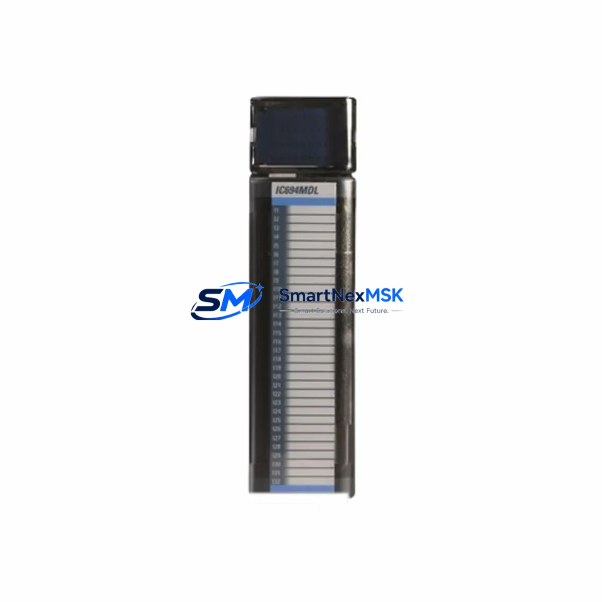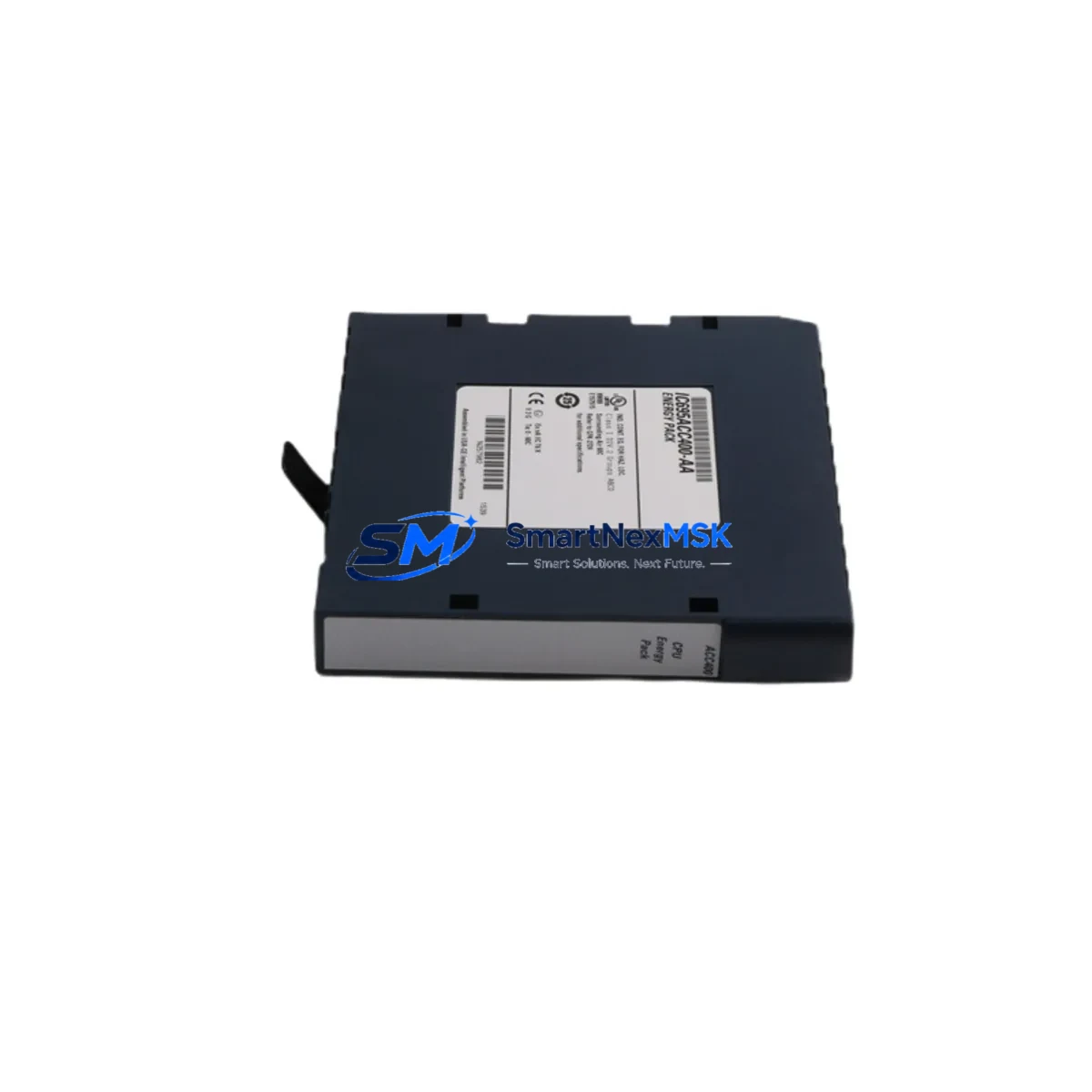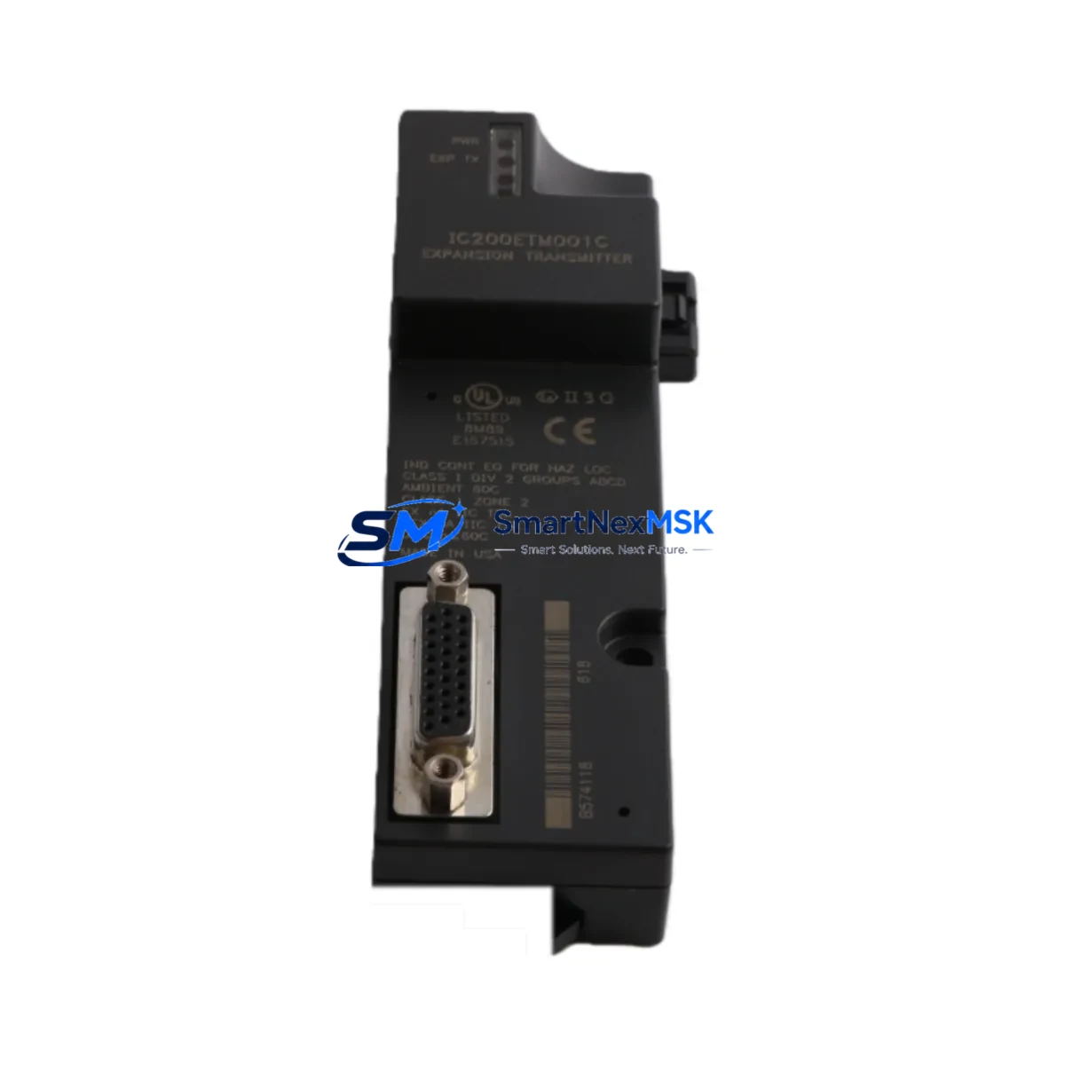
GE IC200ETM001 Retrofit-Ready Ethernet Module for VersaMax Control Systems
The GE IC200ETM001 is a 10/100 Mbps Ethernet Transmitter Module designed for the GE VersaMax distributed I/O platform. As legacy VersaMax installations approach end-of-life support cycles, the IC200ETM001 remains one of the most sought-after retrofit components for engineers tasked with modernizing existing control architectures without full system replacement. Whether you are replacing a failed unit on an active production line, upgrading communications from serial-based protocols to Ethernet, or expanding an existing VersaMax rack to support SCADA integration, the IC200ETM001 provides a direct, low-disruption path forward.
SMARTNEXMSK maintains verified stock of the IC200ETM001 sourced from authorized distribution channels. Each unit undergoes pre-shipment functional testing and ships with a 12-month warranty covering manufacturing defects and operational failures under normal industrial conditions.
Upgrade Compatibility Table
| Parameter | IC200ETM001 Specification | Retrofit Notes |
|---|---|---|
| Communication Interface | 10/100 Mbps Ethernet (RJ-45) | Replaces IC200SET001 serial module; requires network switch port |
| Protocol Support | Modbus TCP, SRTP, EGD | Verify SCADA/HMI driver supports Modbus TCP or SRTP before cutover |
| Backplane Compatibility | VersaMax NIU / Expansion Racks | Compatible with IC200CHS002, IC200CHS005, IC200CHS022 carrier bases |
| Power Consumption | 1.5 W (from backplane) | Verify IC200PWR002 or IC200PWR102 power budget before installation |
| Module Addressing | Configured via GE Proficy Machine Edition | Module slot address must match original hardware configuration table |
| Installation Form Factor | Single-slot VersaMax module | Direct slot replacement; no bracket or adapter required |
| HMI Compatibility | Supports SRTP for iFIX, CIMPLICITY, and third-party HMI | Update HMI communication driver and IP address after replacement |
| Warranty | 12 Months | Covers manufacturing defects; includes pre-shipment functional test report |
Retrofit Planning for Existing Automation Systems
Successful integration of the IC200ETM001 into an existing VersaMax system begins well before the physical module swap. Engineers should start by auditing the current rack configuration, documenting every module slot assignment across the IC200CHS002 or IC200CHS022 carrier base. Pay particular attention to the IC200PWR002 power supply capacity — adding an Ethernet module increases backplane current draw, and systems running near the power budget limit may require an upgrade to the IC200PWR102 high-capacity supply.
On the communications side, the IC200ETM001 replaces older serial-based connectivity solutions such as the IC200SET001 SNP/SNPX serial module. Before decommissioning the serial link, confirm that all upstream SCADA nodes, historian servers, and HMI terminals — including any iFIX or CIMPLICITY workstations — have been reconfigured to use Modbus TCP or SRTP over Ethernet. If the plant network uses managed switches, coordinate with the IT or OT network team to assign a static IP address and configure the appropriate VLAN for the new module.
For systems that include remote I/O expansion, verify that the IC200ETM001 is correctly recognized as the network interface unit within GE Proficy Machine Edition. The hardware configuration table must reflect the exact slot position of the module, and any changes to the I/O map — including additions of IC200MDL740 discrete output modules or IC200ALG264 analog input modules — must be compiled and downloaded to the IC200CPUE05 or IC200CPUE05-AA CPU before the new module is powered on.
Wiring adaptation is generally straightforward since the IC200ETM001 uses a standard RJ-45 Ethernet connection rather than terminal block wiring. However, if the control cabinet was originally designed for serial cabling, additional cable management and conduit routing may be required to accommodate the Ethernet patch cable run to the nearest network switch. Shielded Cat6 cable is recommended in environments with high electromagnetic interference from variable frequency drives or servo amplifiers.
Finally, document the pre-retrofit program backup from the existing CPU using Proficy Machine Edition before any hardware changes are made. Store the backup on a secure engineering workstation and verify the program version matches the as-built documentation. This ensures that if any issue arises during commissioning, the original logic can be restored without delay.
Downtime Control During System Migration
Minimizing unplanned downtime during a VersaMax Ethernet module retrofit requires a structured cutover plan. The recommended approach is to perform all software preparation — IP address assignment, HMI driver reconfiguration, and program compilation — during scheduled maintenance windows before the physical swap takes place. This reduces the live cutover to a single slot replacement and a brief communications verification sequence.
Before powering down the rack, place the CPU in Stop mode and confirm that all field outputs are in a safe state. If the system controls critical processes such as conveyor drives, pneumatic actuators, or temperature control loops, coordinate with operations to ensure manual overrides or bypass procedures are in place. After installing the IC200ETM001 and restoring power, use the module’s status LEDs to confirm Ethernet link establishment before attempting a program download or online monitoring session.
For systems where continuous operation is required, consider staging a parallel VersaMax rack with the IC200ETM001 pre-configured and tested offline. This hot-standby approach allows the cutover to be completed in minutes rather than hours, preserving production continuity while the legacy serial module is retired. Once the new Ethernet link is confirmed stable, the original IC200SET001 or equivalent serial module can be removed and the rack configuration finalized.
Keep a commissioning checklist that covers: Ethernet link status confirmation, SCADA tag polling verification, HMI screen data refresh validation, alarm and event logging continuity, and a 30-minute supervised run at normal production speed before signing off on the retrofit. This structured approach protects both the control program integrity and the physical process from unexpected interruptions.
Retrofit Support FAQ
Q: Is the IC200ETM001 a direct drop-in replacement for the IC200SET001 serial module?
A: The IC200ETM001 occupies the same single-slot form factor in the VersaMax rack and connects to the same backplane bus. However, it uses Ethernet (RJ-45) rather than serial terminals, so the communication driver in your SCADA or HMI system must be updated from SNP/SNPX serial to Modbus TCP or SRTP. Physical installation is straightforward; the protocol migration requires software reconfiguration.
Q: What pre-shipment testing does SMARTNEXMSK perform on the IC200ETM001?
A: Each IC200ETM001 unit is powered on and verified for Ethernet link establishment, module status LED operation, and basic communication response before shipment. A functional test record is available upon request. All units ship with a 12-month warranty covering manufacturing defects and operational failures under normal industrial use conditions.
Q: How do I configure the IP address for the IC200ETM001 after installation?
A: IP address assignment is performed through GE Proficy Machine Edition using the hardware configuration tool. Connect a programming cable or use an existing Ethernet path to the CPU, open the hardware configuration, navigate to the ETM001 module properties, and enter the desired static IP address, subnet mask, and gateway. Download the updated configuration to the CPU and cycle power to apply the new network settings.
Q: Can the IC200ETM001 support simultaneous connections from multiple SCADA clients or HMI stations?
A: Yes. The IC200ETM001 supports multiple concurrent Ethernet connections, allowing a SCADA server, an HMI terminal, and an engineering workstation running Proficy Machine Edition to communicate with the VersaMax system simultaneously. Confirm the number of supported connections in the module’s datasheet and plan your network topology accordingly to avoid polling conflicts or timeout errors during peak communication load.
© 2026 SMARTNEXMSK. All rights reserved.
Original Source: https://smartnexmsk.com
Contact: [email protected] | +86 18259474341