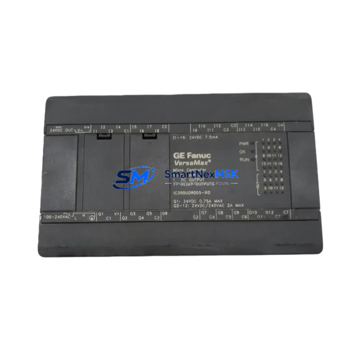
GE IC200UDR005-BD Retrofit-Ready Micro PLC for VersaMax Control Systems
The GE IC200UDR005-BD is a 14-point DC input / relay output VersaMax Micro PLC controller designed for compact machine control and legacy system modernization. As GE Automation (now Emerson) continues to transition its installed base toward newer platforms, the IC200UDR005-BD has become one of the most sought-after retrofit components for engineers managing aging VersaMax Micro installations. SMARTNEXMSK maintains verified stock of this unit, fully tested and backed by a 12-month warranty, to support your planned or emergency replacement projects.
Upgrade Compatibility Table
| Parameter | IC200UDR005-BD | Retrofit Notes |
|---|---|---|
| CPU Type | VersaMax Micro, 14-Point | Direct replacement for IC200UDR005 base variant |
| Digital Inputs | 8 × 24VDC | Verify field wiring polarity before swap |
| Digital Outputs | 6 × Relay (2A/point) | Check load ratings vs. original relay specs |
| Power Supply | 24VDC nominal | Confirm panel PSU capacity ≥ 3A for module + I/O |
| Communication Port | RS-232 (Port 1) | Compatible with IC200CBL001 programming cable |
| Mounting | DIN rail or panel | Same footprint as IC200UDR005; no bracket change needed |
| Programming Software | Proficy Machine Edition 8.x+ | Existing .mep project files load without conversion |
| Firmware Compatibility | VersaMax Micro firmware ≥ 2.10 | Upgrade firmware via serial port before commissioning |
| Warranty | 12-Month Warranty — covered against manufacturing defects from date of shipment | |
Retrofit Planning for Existing Automation Systems
Replacing an IC200UDR005-BD in a live production environment requires careful pre-planning across several system layers. Begin by documenting the existing program logic using Proficy Machine Edition — export the full .mep project file and store it offline before any hardware is removed. If the original unit is still partially functional, use the online monitoring mode to capture current I/O states and reference tag values.
On the power side, verify that the 24VDC panel power supply — often a Phoenix Contact QUINT or similar DIN-rail unit — can sustain the inrush current during module boot. The IC200UDR005-BD draws approximately 200mA at 24VDC; factor in connected field devices on the relay outputs. If the control cabinet also houses an IC200PWR002 or IC200PWR101 expansion power supply feeding additional I/O modules, confirm that the total load budget remains within rated capacity after the swap.
Terminal wiring on the IC200UDR005-BD uses a removable 18-pin connector block. Label all field wires before disconnection and photograph the terminal layout. The connector is keyed, but verifying wire-by-wire against the original panel drawing prevents costly miswiring. Pay particular attention to the common terminals for relay output groups — incorrect common wiring is the leading cause of commissioning failures on relay-output Micro PLCs.
If the system communicates upstream to a SCADA or HMI — such as a Beijer Electronics E-series, Weintek cMT, or legacy GE QuickPanel — verify that the RS-232 serial link parameters (baud rate, parity, stop bits, SNP or SNPX protocol) are preserved in the replacement unit’s configuration. The IC200UDR005-BD supports SNP slave mode natively; no driver change is required on the HMI side provided the communication parameters match exactly.
For systems that include expansion I/O — such as the IC200MDL640 discrete input module or IC200MDL741 relay output module mounted on an IC200CHS002 or IC200CHS012 expansion carrier — confirm that the module address assignments in the hardware configuration match the physical slot positions. A mismatch between the hardware configuration and the physical rack layout will cause a configuration fault on first power-up. Use the Hardware Configuration tool in Proficy Machine Edition to validate slot assignments before going online.
Where the VersaMax Micro system is being migrated toward a newer platform — such as the PACSystems RX3i or a third-party Modbus TCP controller — consider retaining the IC200UDR005-BD as an interim bridge controller while the new system is commissioned in parallel. This staged approach allows the production line to remain operational during the transition, with cutover occurring during a planned maintenance window rather than an emergency shutdown.
Downtime Control During System Migration
Minimizing unplanned downtime during a VersaMax Micro replacement begins with a structured pre-swap checklist. Before removing the IC200UDR005-BD, place all connected field outputs in a safe state — either through the PLC’s Stop mode output behavior configuration or by manually de-energizing the relay output commons at the terminal block. This prevents actuators, solenoids, or motor starters from receiving unintended commands during the hardware swap.
Back up the program to both the programming laptop and a USB drive. If the replacement unit ships with a blank memory, the program must be downloaded via the IC200CBL001 RS-232 cable before the unit is placed in Run mode. Confirm that the firmware version on the replacement IC200UDR005-BD matches or exceeds the version on the original unit — a lower firmware version may not support all instructions used in the existing program, resulting in a program load error.
After download, perform a controlled power cycle and monitor the I/O status table in Proficy Machine Edition online mode. Verify that all discrete inputs reflect the correct field states before enabling outputs. For relay output points, use a multimeter to confirm continuity across each output terminal pair under program control before reconnecting field loads. This step-by-step commissioning approach typically allows a full IC200UDR005-BD swap to be completed within a 2–4 hour maintenance window, even in complex multi-module configurations.
Retrofit Support FAQ
Q1: Is the IC200UDR005-BD a direct drop-in replacement for the IC200UDR005?
A: Yes. The -BD suffix denotes a board-level revision with no functional or wiring differences from the base IC200UDR005. The same program, terminal wiring, and communication settings apply without modification.
Q2: What programming cable is required for commissioning?
A: The IC200CBL001 RS-232 serial cable is the standard programming cable for all VersaMax Micro units. Connect from the PC COM port (or USB-to-serial adapter) to Port 1 on the IC200UDR005-BD. Set the port parameters to 19200 baud, 8N1, SNP protocol in Proficy Machine Edition.
Q3: Does SMARTNEXMSK test units before shipment?
A: Yes. Every IC200UDR005-BD unit undergoes power-on functional verification and I/O point testing prior to shipment. Units are shipped with a 12-month warranty covering manufacturing defects. A test report is available upon request.
Q4: Can this unit be used in a system that also has IC200MDL640 or IC200MDL741 expansion modules?
A: Yes. The IC200UDR005-BD supports expansion I/O via the VersaMax Micro expansion bus. Expansion modules mounted on IC200CHS002 or IC200CHS012 carriers are fully compatible, provided the hardware configuration in Proficy Machine Edition correctly reflects the physical slot layout.
© 2026 SMARTNEXMSK. All rights reserved.
Original Source: https://smartnexmsk.com
Contact: [email protected] | +86 18259474341