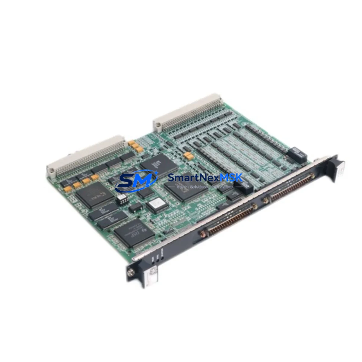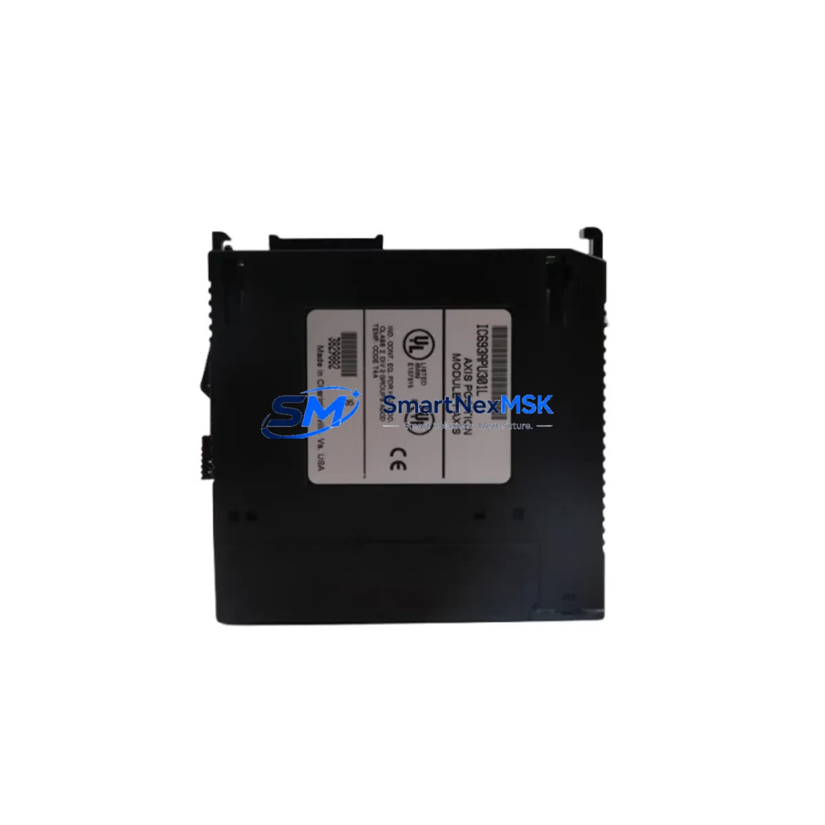
GE IC693APU301 Retrofit-Ready Axis Module for Series 90-30 Control Systems
The GE IC693APU301 is a single-axis positioning module designed for the GE Series 90-30 programmable logic controller platform. As legacy Series 90-30 systems approach end-of-support milestones, the IC693APU301 remains one of the most sought-after retrofit components for facilities managing aging motion control infrastructure. Whether you are replacing a failed unit on an active production line, upgrading a control cabinet to extend service life, or migrating from an earlier IC693APU300 revision, this module provides a verified drop-in solution with minimal re-engineering overhead.
The IC693APU301 occupies a single slot in the Series 90-30 five-slot or ten-slot baseplate and interfaces directly with the CPU rack backplane. It supports incremental encoder feedback, high-speed pulse output for stepper or servo drive command, and onboard motion profile execution independent of the main CPU scan cycle. Engineers replacing this module in the field should confirm the existing IC693CHS391 or IC693CHS397 rack has an available I/O slot adjacent to the power supply module, as the APU301 draws additional backplane current that must be accounted for in the rack power budget alongside other installed modules such as the IC693MDL645 discrete input module or IC693ALG221 analog output module.
Before removing the legacy unit, record all axis parameters stored in the CPU program — including encoder counts per unit, acceleration ramps, deceleration ramps, home offset, and software travel limits. These values are not retained in the module itself and must be re-entered via the programming software after installation. Users running GE Proficy Machine Edition or the legacy Logicmaster 90 programming environment should verify that the APU301 function block library version matches the installed CPU firmware, particularly when the host controller is an IC693CPU374 or IC693CPU375 processor module.
Upgrade Compatibility Table
| Parameter | IC693APU300 (Legacy) | IC693APU301 (Current) |
|---|---|---|
| Axes Supported | 1 axis | 1 axis |
| Encoder Input | Incremental, 5 V differential | Incremental, 5 V differential |
| Max Pulse Output | 1 MHz | 1 MHz |
| Rack Slot Requirement | 1 slot, Series 90-30 baseplate | 1 slot, Series 90-30 baseplate |
| Backplane Interface | Series 90-30 standard | Series 90-30 standard (compatible) |
| Communication Protocol | Backplane I/O bus | Backplane I/O bus |
| CPU Compatibility | IC693CPU331–374 | IC693CPU331–375 (extended) |
| Terminal Wiring | 40-pin removable terminal block | 40-pin removable terminal block (direct swap) |
| Firmware Requirement | Logicmaster 90 v9.x | Proficy ME or Logicmaster 90 v9.x+ |
| Replacement Recommendation | Direct replacement with APU301 | — |
| Commissioning Focus | Re-enter axis parameters post-swap | Verify encoder wiring polarity and home sequence |
| Warranty | N/A (discontinued) | 12-Month Warranty included |
Retrofit Planning for Existing Automation Systems
A successful IC693APU301 retrofit begins well before the module arrives on site. Start by auditing the full rack assembly: confirm the IC693CHS391 five-slot baseplate or IC693CHS397 ten-slot baseplate has adequate free slots and that the IC693PWR321 or IC693PWR330 power supply module can support the additional current draw. In multi-rack configurations connected via the IC693CBL300 expansion cable, verify that the remote rack’s power budget is not already at capacity before relocating the positioning axis to a remote chassis.
Terminal wiring on the IC693APU301 uses a 40-pin removable connector. When replacing an IC693APU300, the existing wiring harness can typically be transferred directly, but technicians should inspect each conductor for insulation fatigue, particularly on encoder feedback lines where signal integrity is critical at high pulse rates. Encoder cable shielding must be grounded at the module end only to prevent ground loops that can corrupt position counts. If the servo drive or stepper driver being commanded is connected via a separate IC693MDL940 relay output module for enable/fault signals, verify that the interlock logic in the CPU program still references the correct I/O addresses after any slot reassignment.
For facilities also upgrading the HMI layer, operators using a QuickPanel or third-party panel connected via the IC693CMM321 communications module should update the HMI screen tags to reflect any address changes introduced during the retrofit. If the control network uses SNP or SRTP protocol over the IC693CMM302 Ethernet module, no protocol migration is required — the APU301 communicates exclusively over the backplane and is transparent to the network layer. However, if the broader modernization roadmap includes migrating to a PACSystems RX3i platform, note that the IC693APU301 is not compatible with the RX3i backplane and a separate VersaMotion or PACSystems motion module would be required for that migration path.
Downtime Control During System Migration
Minimizing unplanned downtime during an IC693APU301 swap requires a structured pre-outage checklist. Before powering down the rack, use the programming terminal connected via IC693CBL301 serial cable or the Ethernet port on the IC693CMM302 to perform a full program upload and save the CPU memory image, including the motion axis data table. Store this backup on an offline engineering workstation — do not rely solely on the module’s internal memory, as axis parameters are CPU-resident.
During the physical swap, the 40-pin terminal block can be removed without disturbing individual wire terminations, which significantly reduces reconnection time. After seating the IC693APU301 in the rack, power up the system and allow the CPU to complete its I/O configuration scan before attempting to enable the axis. Confirm that the module’s status LEDs indicate normal operation before downloading the saved program. Re-enter all axis parameters — counts per unit, velocity limits, acceleration profiles, and home offset — and run a dry-cycle test with the drive in torque-limited mode before returning the machine to production. This staged commissioning approach protects the original program logic and maintains field control continuity throughout the migration window, typically allowing a complete swap and verification within a two-to-four hour planned maintenance window.
Retrofit Support FAQ
Q: Is the IC693APU301 a direct drop-in replacement for the IC693APU300?
A: Yes. The IC693APU301 is the current production revision of the IC693APU300 and uses the same 40-pin terminal block pinout and backplane slot footprint. Axis parameters must be re-entered after installation as they are stored in CPU memory, not in the module itself.
Q: What wiring changes are required during the retrofit?
A: In most cases, no wiring changes are needed. The removable 40-pin terminal block transfers directly from the old module to the new one. Technicians should inspect encoder feedback cables for wear and verify shield grounding before powering up.
Q: How is compatibility with the host CPU verified before installation?
A: Confirm the CPU firmware version supports the APU301 function block library. CPUs from IC693CPU331 through IC693CPU375 are compatible. Use Proficy Machine Edition or Logicmaster 90 to check the firmware revision and update if necessary before the swap.
Q: What does the 12-month warranty cover?
A: Each IC693APU301 unit supplied by SMARTNEXMSK is covered by a 12-month warranty against manufacturing defects and functional failure under normal operating conditions. Pre-shipment functional testing is performed on every unit. Warranty claims are processed via [email protected] with a return authorization number issued within one business day.
© 2026 SMARTNEXMSK. All rights reserved.
Original Source: https://smartnexmsk.com
Contact: [email protected] | +86 18259474341