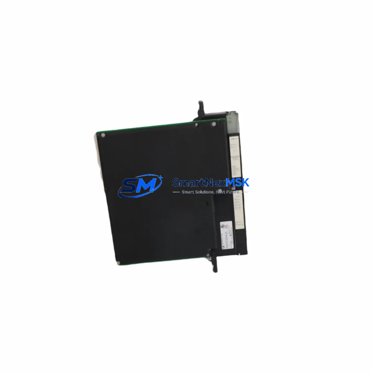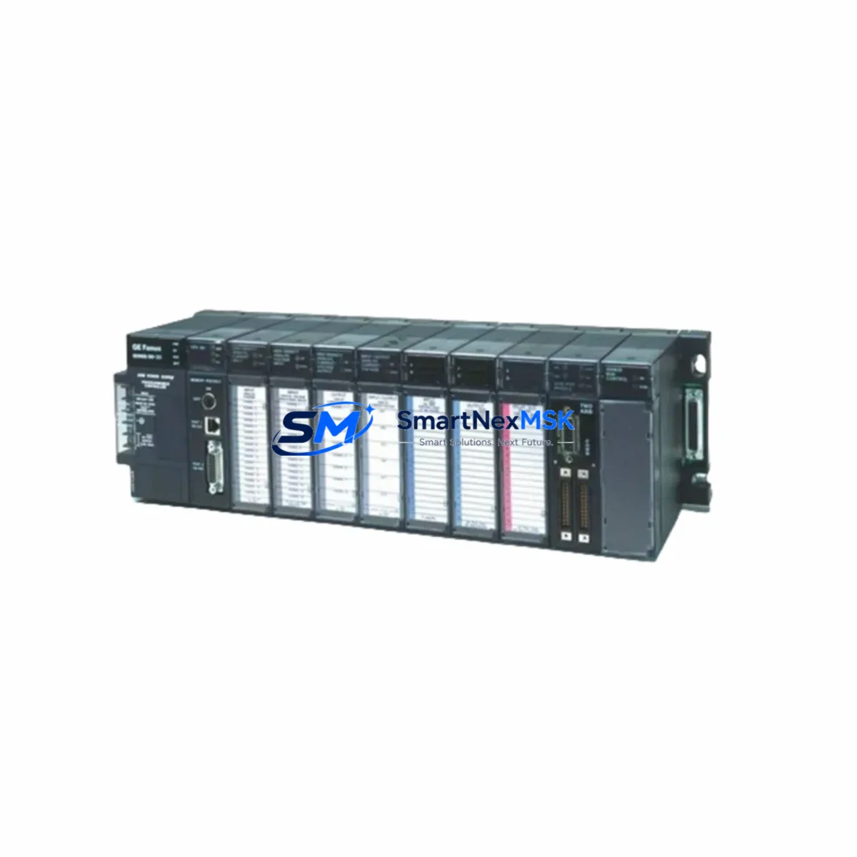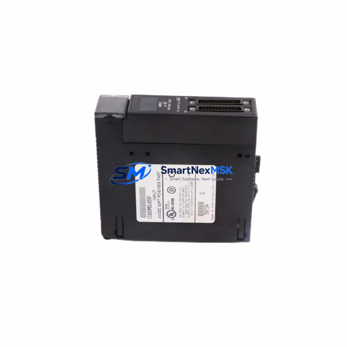
GE IC693MDL655 Retrofit-Ready Discrete Input Module for Series 90-30 Control Systems
The GE IC693MDL655 is a 32-point, 24VDC discrete input module engineered for the GE Fanuc Series 90-30 programmable logic controller platform. As legacy Series 90-30 systems approach end-of-life and original spare parts become increasingly scarce, the IC693MDL655 remains one of the most sought-after retrofit and replacement components for industrial facilities seeking to extend the operational life of their existing control infrastructure without committing to a full platform migration.
Whether you are replacing a failed module in a running production line, upgrading an aging control cabinet, or executing a phased modernization of a multi-rack Series 90-30 system, the IC693MDL655 provides a verified drop-in solution that preserves your existing wiring, rack architecture, and PLC program logic. This module is compatible with the IC693CHS391, IC693CHS392, and IC693CHS393 5-slot, 10-slot, and expansion chassis configurations, and interfaces directly with the IC693CPU374 and IC693CPU375 central processing units without requiring firmware changes or program re-compilation.
Upgrade Compatibility Table
| Parameter | IC693MDL655 Specification | Retrofit Notes |
|---|---|---|
| Input Points | 32 points (2 × 16-point groups) | Direct replacement for IC693MDL654 (16-pt); verify address mapping |
| Input Voltage | 24VDC (nominal), 10–30VDC range | Confirm field device supply voltage before installation |
| Backplane Interface | Series 90-30 parallel backplane bus | Compatible with all IC693CHS3xx chassis generations |
| Module Slot | Any I/O slot in Series 90-30 chassis | Slot address must match original configuration in CPU memory |
| Terminal Block | 40-pin removable terminal block (IC693ACC300) | Existing field wiring can be transferred without re-termination |
| Communication Protocol | Backplane parallel I/O (no Ethernet/serial config required) | No protocol migration needed; compatible with IC693CMM321 and IC693CMM311 comm modules |
| CPU Compatibility | IC693CPU374, IC693CPU375, IC693CPU364, IC693CPU363 | No program re-download required if slot address is preserved |
| Replacement Path | Replaces IC693MDL654, IC693MDL640, IC693MDL645 | Verify I/O table reference addresses in Proficy Machine Edition |
| Commissioning Tool | GE Proficy Machine Edition (PME) Logic Developer | Use I/O Force function to verify all 32 points before restart |
| Warranty | 12-Month Warranty | Covers manufacturing defects; includes pre-shipment functional test |
Retrofit Planning for Existing Automation Systems
A successful IC693MDL655 retrofit begins well before the module arrives on-site. The first step is a thorough audit of the existing Series 90-30 rack configuration. Engineers should document the current slot assignments for all installed modules — including the IC693PWR321 or IC693PWR330 power supply module, any IC693MDL740 or IC693MDL741 discrete output modules sharing the same chassis, and any IC693ALG220 or IC693ALG221 analog input modules that may be co-located in the same rack. Power budget calculations are essential: the IC693MDL655 draws 85mA from the 5VDC backplane bus, and the total chassis load must remain within the rated output of the installed power supply.
Terminal block wiring is one of the most critical steps in the replacement process. The IC693MDL655 uses the IC693ACC300 40-pin removable terminal block, which allows field wiring to be disconnected as a single assembly and transferred to the new module without disturbing individual wire terminations. Before removal, photograph or document the existing wiring layout and verify that all field device commons are correctly grouped by input group (Group 1: points 1–16; Group 2: points 17–32). Incorrect common wiring is a frequent source of commissioning errors during discrete input module replacements.
Module address configuration is handled entirely through the CPU’s I/O configuration table, stored in the IC693CPU374 or IC693CPU375 memory. When the IC693MDL655 is installed in the same physical slot as the original module, the CPU will automatically recognize it at power-up without requiring a hardware configuration change in Proficy Machine Edition. However, if the slot position has changed — for example, due to chassis reconfiguration or the addition of an IC693CHS392 expansion chassis — the I/O table must be updated and the program re-downloaded to the CPU before the module will respond correctly.
For systems that include an IC693CMM321 Ethernet communications module or an IC693CMM311 serial communications module, no changes to the communications configuration are required when replacing a discrete input module. The IC693MDL655 operates entirely on the backplane parallel bus and does not interact with the communications layer. Similarly, HMI screens built on GE iFIX, Wonderware, or third-party SCADA platforms that reference the input addresses associated with this module will continue to function without modification, provided the I/O address mapping is preserved.
Downtime Control During System Migration
Minimizing unplanned downtime is the primary operational concern during any Series 90-30 module replacement. The IC693MDL655 supports hot-insertion in chassis that are powered and running, but GE Fanuc’s recommended practice is to place the CPU in Stop mode before removing or inserting any I/O module to prevent spurious output transitions and protect the integrity of the running program. For critical production environments where even a brief Stop mode transition is unacceptable, a parallel commissioning approach is recommended: install the replacement module in a spare slot of an identical chassis, verify all 32 input points using the I/O Force function in Proficy Machine Edition, and then execute the physical swap during a scheduled micro-shutdown.
Before initiating the swap, use PME’s online monitoring function to capture a snapshot of the current I/O status table. This snapshot serves as a baseline for post-installation verification and allows technicians to confirm that all field devices are reporting correctly after the module is replaced. Pay particular attention to any inputs that are used as interlocks or safety permissives in the PLC program — these should be individually verified using a calibrated signal source before the CPU is returned to Run mode.
Program logic compatibility is not a concern when replacing the IC693MDL655 on a like-for-like basis, as the module’s I/O reference addresses are defined in the CPU configuration rather than in the module hardware itself. However, if the replacement is part of a broader migration from Series 90-30 to a PACSystems RX3i platform, the program will need to be converted using GE’s Conversion Utility within Proficy Machine Edition, and all I/O reference addresses will need to be remapped to the new RX3i I/O module assignments. In this scenario, the IC694MDL660 (RX3i 32-point 24VDC input module) is the functional equivalent of the IC693MDL655 and is the recommended migration target.
Retrofit Support FAQ
Q1: Is the IC693MDL655 a direct drop-in replacement for the IC693MDL654?
The IC693MDL654 is a 16-point 24VDC discrete input module, while the IC693MDL655 provides 32 points. Physical dimensions and backplane connector are identical, allowing installation in the same slot. However, the I/O configuration table in the CPU must be updated to reflect the expanded point count, and any HMI or SCADA screens referencing the upper 16 points (17–32) must be verified for correct address mapping before returning to production.
Q2: What commissioning steps are required after installing the IC693MDL655?
After physical installation and terminal block reconnection, power up the chassis and use Proficy Machine Edition to go online with the CPU. Navigate to the I/O configuration table and verify that the module is recognized in the correct slot. Use the I/O Force function to individually activate each of the 32 input points and confirm correct status indication in the PLC program. Document all forced values and release forces before returning the CPU to Run mode. A full functional test of all field devices connected to the module is recommended before resuming production.
Q3: Can the IC693MDL655 be used in an IC693CHS392 expansion chassis connected via the IC693CBL300 bus expansion cable?
Yes. The IC693MDL655 is fully compatible with all Series 90-30 chassis types, including the IC693CHS391 (5-slot), IC693CHS392 (10-slot), and IC693CHS393 (10-slot with power supply). When installed in an expansion chassis connected via the IC693CBL300 or IC693CBL301 bus expansion cable, the module is addressed as part of the expanded I/O table and requires no special configuration beyond correct slot assignment in the CPU’s hardware configuration.
Q4: What does the 12-month warranty cover, and is pre-shipment testing performed?
Every IC693MDL655 unit shipped by SMARTNEXMSK undergoes a pre-shipment functional test that verifies backplane communication, input point response, and LED status indication across all 32 channels. The 12-month warranty covers manufacturing defects and functional failures under normal operating conditions. Units are shipped with test documentation upon request. For expedited replacement under warranty, contact our technical support team with the unit serial number and a description of the observed fault.
© 2026 SMARTNEXMSK. All rights reserved.
Original Source: https://smartnexmsk.com
Contact: [email protected] | +86 18259474341