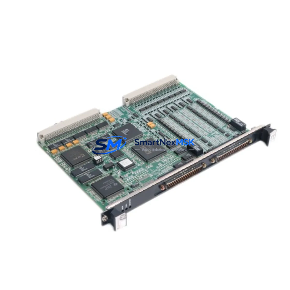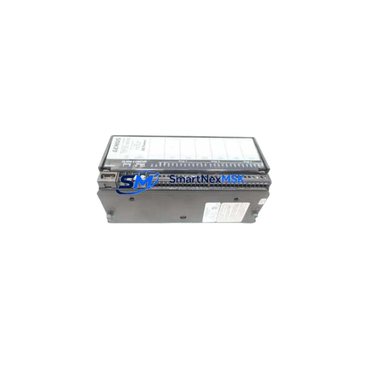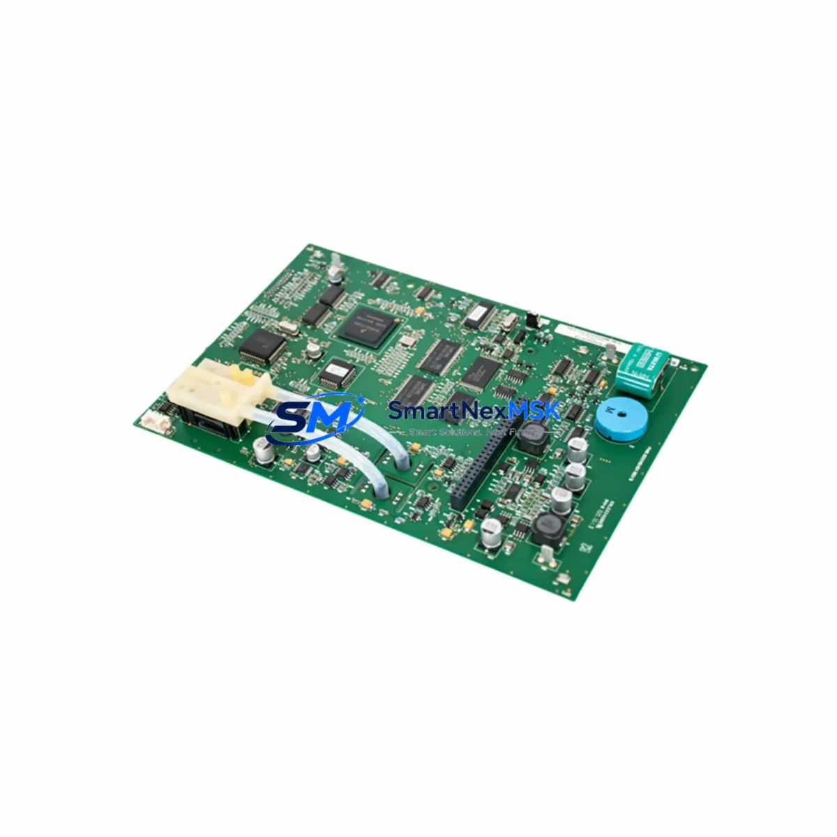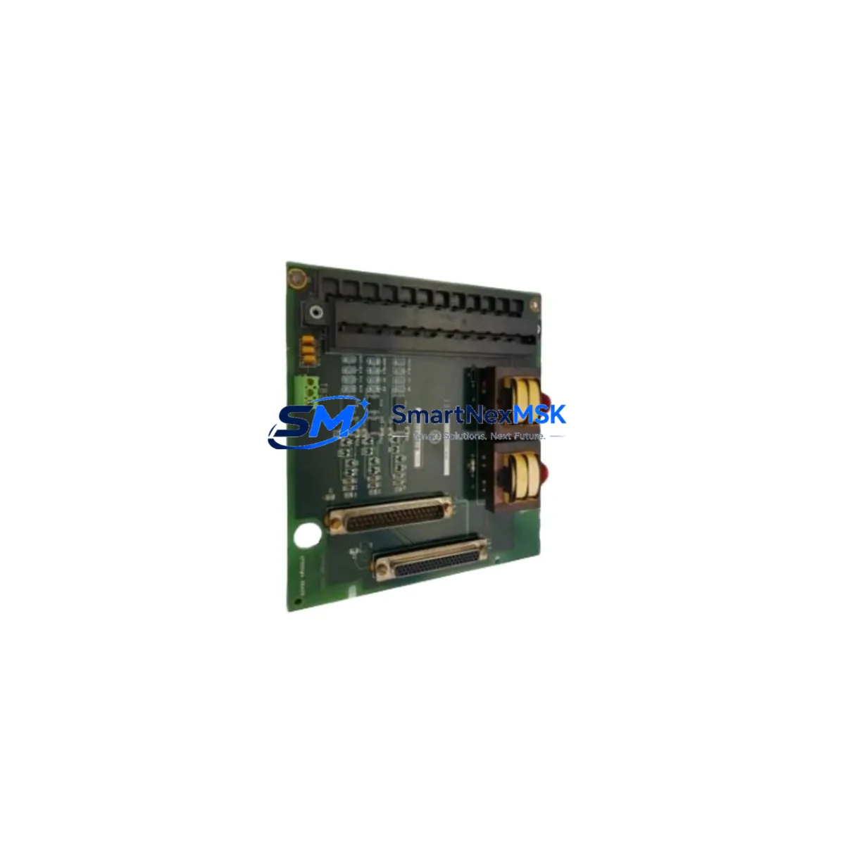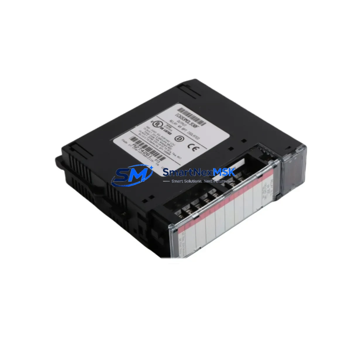
GE IC693MDL930 Retrofit-Ready Discrete Output Module for Series 90-30 Control Systems
The GE IC693MDL930 is a 16-point, 120VAC discrete output module engineered for the GE Series 90-30 programmable logic controller platform. As legacy Series 90-30 systems approach end-of-life and spare parts become increasingly scarce, the IC693MDL930 remains one of the most sought-after retrofit-ready replacements for aging output modules in continuous-process, discrete manufacturing, and utility control applications. Whether you are upgrading a control cabinet, restoring a production line after an unplanned failure, or executing a planned migration from an obsolete output card, this module delivers verified electrical compatibility, reliable switching performance, and a direct backplane fit within the IC693 rack architecture.
Each IC693MDL930 unit shipped by SMARTNEXMSK undergoes pre-shipment functional testing, including output channel verification, backplane communication handshake, and isolation resistance checks. The module is supplied with a 12-month warranty covering manufacturing defects and functional failures under normal operating conditions.
Upgrade Compatibility Table
| Parameter | IC693MDL930 Specification | Retrofit Notes |
|---|---|---|
| Output Type | Discrete, 120VAC | Verify field device voltage matches 120VAC; not compatible with 24VDC loads without relay interposing |
| Output Points | 16 points | Direct replacement for other 16-point AC output modules in the 90-30 family |
| Backplane Interface | IC693 5-slot / 10-slot rack | Compatible with IC693CHS391, IC693CHS392, IC693CHS393 racks; verify slot addressing in CPU configuration |
| Installation | Hot-swap capable (with CPU support) | Confirm CPU firmware version supports hot-swap; older IC693CPU311 revisions may require rack power-down |
| Communication | Backplane parallel bus | No protocol migration required; module address set via CPU configuration tool (Proficy Machine Edition) |
| Replacement Candidates | IC693MDL930, IC693MDL931, IC693MDL940 | Cross-reference output current rating and point count before substitution |
| Debugging Focus | Output channel mapping, I/O table offset | Verify %Q address assignments in ladder logic after module swap |
| Warranty | 12 Months | Covers functional failure; excludes physical damage from incorrect wiring or overvoltage |
Retrofit Planning for Existing Automation Systems
Successful integration of the IC693MDL930 into an existing Series 90-30 control system requires a structured pre-installation review. Begin by auditing the current rack configuration: identify the IC693CHS391 or IC693CHS392 chassis slot occupied by the outgoing module, and confirm that the replacement module’s I/O address block aligns with the existing CPU configuration stored in the IC693CPU364 or IC693CPU374 controller. If the system uses an IC693CMM321 communications module for Genius Bus or an IC693CMM311 for Ethernet, verify that the output module’s slot assignment does not conflict with the communications module’s memory map.
Terminal wiring is a critical checkpoint. The IC693MDL930 uses a removable terminal block, which simplifies field replacement without rewiring. However, technicians should confirm that the existing field wiring — typically 14–18 AWG for 120VAC loads — is correctly torqued and that the neutral conductor is properly landed. Where the outgoing module used a different terminal block pitch or connector style (as may be the case when replacing an IC693MDL931 or an older IC693MDL940), an adapter or re-termination may be required.
Power budget verification is essential before commissioning. The IC693MDL930 draws its logic power from the IC693PWR321 or IC693PWR330 power supply module via the backplane. Calculate the total backplane current draw across all installed modules — including any IC693ALG220 analog input modules, IC693MDL654 discrete input modules, and the CPU itself — to confirm the power supply is not operating near its rated capacity. Overloaded power supplies are a leading cause of intermittent faults during retrofit commissioning.
For systems that include an IC693APU300 axis positioning module or an IC693DSM302 motion control module sharing the same rack, confirm that the output module’s slot does not interfere with the motion module’s dedicated I/O reservation. After physical installation, use Proficy Machine Edition or the legacy Logicmaster 90 programming software to download the existing program, verify the hardware configuration matches the physical rack layout, and perform a forced-output test on each of the 16 output channels before returning the system to automatic mode.
Downtime Control During System Migration
Minimizing production downtime during an IC693MDL930 swap requires preparation before the maintenance window opens. Export and archive the current CPU program from the IC693CPU364 or IC693CPU374 using Proficy Machine Edition, and store a verified backup on an offline programming device. If the system uses an IC693CMM321 Genius Bus Communications Module, document the Genius block addresses and I/O map before disconnecting power, as some older CPU revisions do not retain configuration across a cold restart without a valid program store.
During the physical swap, the removable terminal block on the IC693MDL930 allows the field wiring to remain connected while the module body is extracted from the rack — significantly reducing reconnection time and the risk of miswiring. After seating the replacement module, restore rack power and allow the IC693PWR321 power supply to stabilize before initiating a CPU warm restart. Monitor the CPU’s I/O fault table for any output channel faults, and use the online monitoring function in Proficy Machine Edition to confirm that all 16 output channels respond correctly to forced commands before releasing the system to operators.
For facilities operating 24/7 with no scheduled downtime windows, a parallel commissioning approach is recommended: install the IC693MDL930 in a spare slot on a test rack alongside an IC693CPU311 or IC693CPU331 controller, load the production program, and validate all output channel assignments before scheduling the live swap. This approach reduces the live maintenance window to under 30 minutes in most cases.
Retrofit Support FAQ
Q1: Is the IC693MDL930 a direct drop-in replacement for the IC693MDL931?
A: The IC693MDL930 and IC693MDL931 share the same backplane connector and rack form factor, but differ in output current rating and isolation configuration. Verify the load current requirements of your field devices before substituting one for the other. In most 120VAC discrete output applications, the IC693MDL930 is a functionally compatible replacement.
Q2: Do I need to modify my ladder logic program after replacing the output module?
A: If the replacement module occupies the same rack slot and the hardware configuration in the CPU is updated to reflect the IC693MDL930, no changes to the %Q output coil addresses in the ladder program are required. However, if the module is installed in a different slot, the I/O address offset must be updated in both the hardware configuration and any affected rungs.
Q3: What wiring checks should I perform before powering up after installation?
A: Confirm that the 120VAC hot and neutral conductors are correctly landed on the output terminal block, that no output terminals are shorted, and that the field device load does not exceed the module’s per-point current rating. Use a multimeter to verify continuity and isolation before applying power. Check that the IC693PWR321 or IC693PWR330 power supply input voltage is within specification.
Q4: What does the 12-month warranty cover, and how is it claimed?
A: The 12-month warranty covers functional failures attributable to manufacturing defects, including output channel failure, backplane communication errors, and internal component faults under normal operating conditions. It does not cover damage resulting from incorrect installation, overvoltage, reverse polarity, or physical impact. To initiate a warranty claim, contact SMARTNEXMSK with the module serial number, a description of the fault, and the original purchase order reference.
© 2026 SMARTNEXMSK. All rights reserved.
Original Source: https://smartnexmsk.com
Contact: [email protected] | +86 18259474341