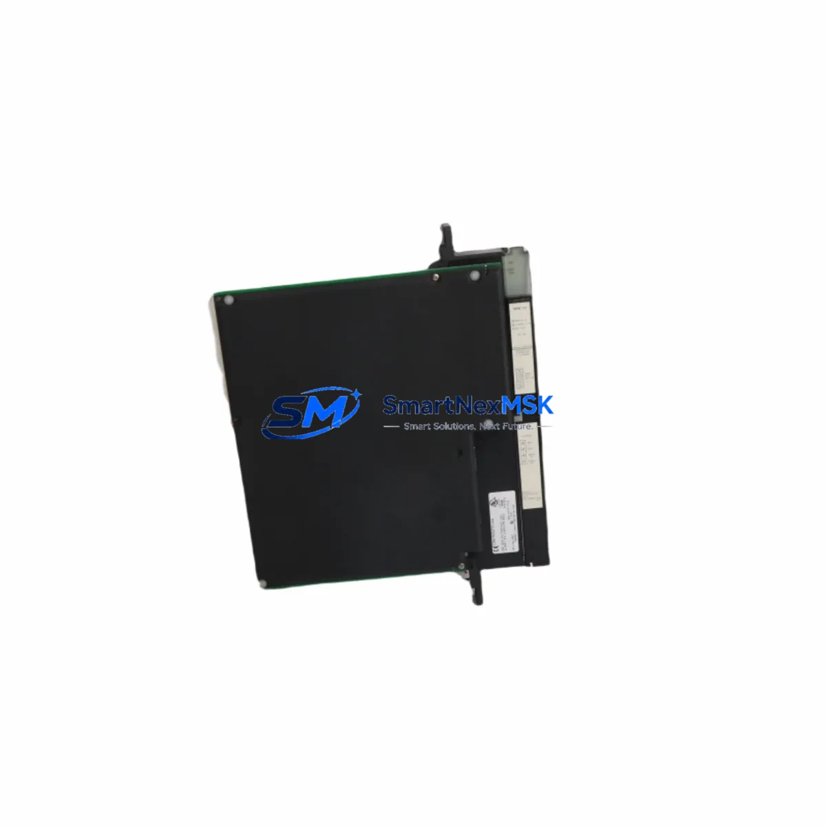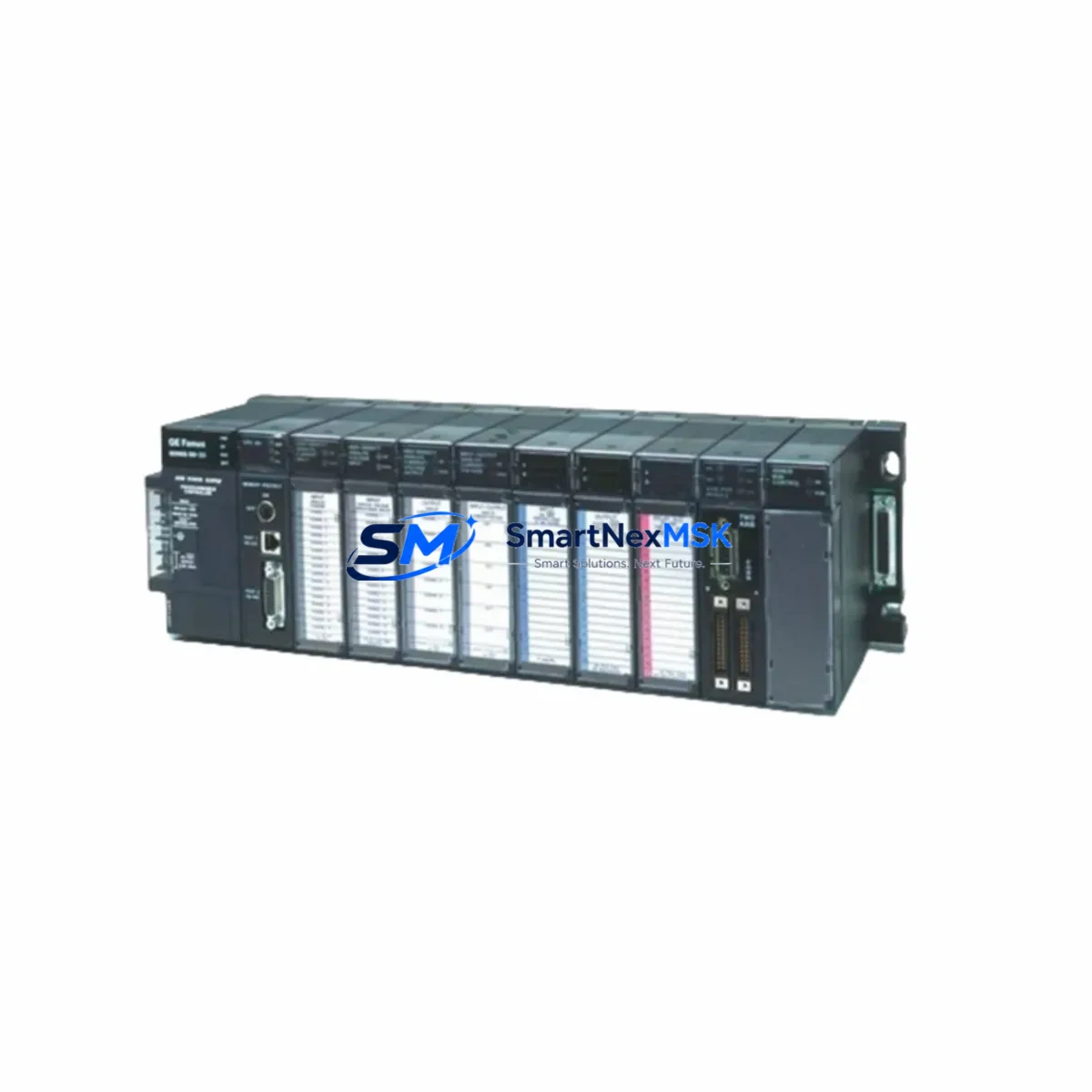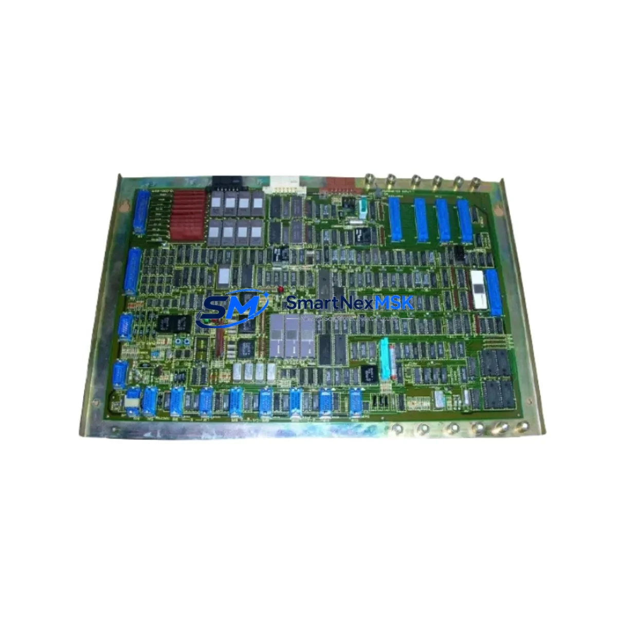
GE IC694MDL660-CC Retrofit-Ready 32-Point Input Module for Series 90-30 Control Systems
The GE Fanuc IC694MDL660-CC is a 32-point, 24VDC discrete input module engineered for the Series 90-30 PLC platform. As legacy Series 90-30 systems approach end-of-life and original GE Fanuc spare parts become increasingly scarce, the IC694MDL660-CC remains one of the most sought-after retrofit-compatible replacements for aging control architectures. Whether you are restoring a discontinued production line, upgrading a control cabinet, or executing a phased migration to a newer automation platform, this module provides a verified drop-in solution that preserves your existing wiring, rack addressing, and ladder logic without requiring a full system redesign.
Sourced from authorized channels and subject to full functional testing prior to shipment, each IC694MDL660-CC unit is backed by a 12-month warranty covering hardware defects and operational failures under normal industrial conditions. Our inventory is maintained to support urgent replacement scenarios, including unplanned downtime events where lead time from the OEM is no longer viable.
Upgrade Compatibility Table
| Parameter | IC694MDL660-CC Specification | Retrofit Notes |
|---|---|---|
| Input Points | 32 points, DC input | Direct replacement for IC694MDL660 base variant; no wiring changes required |
| Input Voltage | 24VDC nominal | Verify field device supply voltage before installation; compatible with standard 24VDC sensor loops |
| Rack Compatibility | IC694CHS392 / IC694CHS398 / IC694CHS782 / IC694CHS784 | Fits all standard Series 90-30 5-slot, 10-slot, and expansion racks; backplane connector is identical |
| Module Addressing | Slot-based I/O addressing via IC694CPU364 / IC694CPU374 / IC694CPU392 | Slot address is preserved; no program modification required if replacing a same-slot module |
| Communication Compatibility | Series 90-30 backplane bus | Compatible with IC694CMM321 (SNP/SNPX), IC694CMM302 (Genius), and IC694PBS301 (PROFIBUS-DP) communication modules |
| Power Consumption | Verify against IC694PWR321 / IC694PWR330 / IC694PWR331 power supply capacity | Confirm rack power budget before adding modules; 32-point input modules draw moderate backplane current |
| Installation Method | Hot-swap capable (with CPU in Stop mode recommended) | Place CPU in Stop mode before module swap to prevent I/O faults; re-enable after seating module |
| Programming Software | Proficy Machine Edition (ME) / Logicmaster 90-30 | Hardware configuration update required in ME if module type changes; I/O table reference remains consistent |
| Warranty | 12 Months | Covers hardware defects and functional failures under standard industrial operating conditions |
Retrofit Planning for Existing Automation Systems
Successful integration of the IC694MDL660-CC into an existing Series 90-30 control system requires a structured pre-installation review. Begin by auditing the current rack configuration: identify the chassis model (IC694CHS392 or IC694CHS398 for standard racks, IC694CHS782 or IC694CHS784 for expansion racks) and confirm available slot positions. If the replacement is slot-for-slot, the CPU’s hardware configuration file in Proficy Machine Edition will not require modification, as the module type and I/O reference addresses remain unchanged.
Next, verify the power supply headroom. The IC694PWR321 (65W) and IC694PWR330 (100W) are the most common power supplies in Series 90-30 cabinets. Adding or replacing a 32-point input module affects the backplane current draw, and the total load across all installed modules — including the IC694CPU364 or IC694CPU374 processor, any IC694CMM321 communication module, and analog I/O modules such as the IC694ALG220 or IC694ALG442 — must remain within the rated output of the installed power supply.
Terminal block wiring is a critical checkpoint. The IC694MDL660-CC uses a 40-pin connector with a standard Series 90-30 field wiring arm. If the existing wiring arm (IC694ACC300 or equivalent) is in good condition, it can be transferred directly to the replacement module, eliminating the need to rewire individual field terminals. This significantly reduces installation time and the risk of wiring errors during the retrofit.
For systems that include a Genius Bus Controller (IC694GBC300 or IC694GBC310), confirm that the I/O block assignments and Genius device numbers are correctly mapped in the hardware configuration. Similarly, if the control system communicates via PROFIBUS-DP through an IC694PBS301 module, verify that the GSD file and slave address assignments are consistent with the replacement module’s slot position.
HMI screens connected via the IC694CMM321 SNP/SNPX port or via an Ethernet module (IC694ETM001) should be reviewed to confirm that all I/O reference tags pointing to the replaced module’s input addresses remain valid. In most slot-for-slot replacements, HMI tag databases require no modification. However, if the module is being relocated to a different slot or rack, all affected reference addresses must be updated in both the PLC program and the HMI project before going live.
Programming cables such as the IC690ACC901 (serial SNP cable) or a standard Ethernet crossover connection to the IC694ETM001 should be prepared in advance to allow rapid program upload, verification, and force-testing of the new module’s input channels during commissioning.
Downtime Control During System Migration
Minimizing unplanned downtime is the primary operational concern when replacing a discrete input module in a live production environment. The recommended approach is to perform the swap during a scheduled maintenance window, with the CPU placed in Stop mode to prevent spurious I/O faults from propagating to the control logic. Before powering down, upload and archive the current PLC program from the IC694CPU364 or IC694CPU392 to a backup file using Proficy Machine Edition. This ensures that the original ladder logic, hardware configuration, and I/O force tables are preserved and can be restored immediately if the replacement module exhibits any unexpected behavior.
Once the IC694MDL660-CC is seated in the rack and the wiring arm is reconnected, perform a controlled power-up sequence: energize the rack, allow the CPU to complete its self-diagnostic cycle, and then transition to Run mode. Use the online monitoring function in Proficy ME to verify that all 32 input channels are reading correctly against known field device states. Force individual inputs if necessary to confirm channel-by-channel integrity before releasing the system to production.
For systems where continuous operation is critical and a redundant rack or hot-standby CPU (such as the IC694CPU374 in a redundancy configuration) is available, the module swap can be coordinated with a controlled switchover to the standby system, reducing the effective downtime to the switchover interval rather than the full replacement duration. Document all steps taken during the retrofit, including pre-swap program backup, module serial number, installation date, and post-swap test results, to support future maintenance audits and warranty claims.
Retrofit Support FAQ
Q: Is the IC694MDL660-CC a direct replacement for the IC694MDL660 without the -CC suffix?
A: Yes. The -CC suffix denotes a conformal-coated variant for enhanced resistance to humidity and airborne contaminants. It is electrically and functionally identical to the base IC694MDL660 and is a direct slot-for-slot replacement. No hardware configuration changes are required in Proficy Machine Edition when substituting one for the other.
Q: What commissioning steps are required after installing the replacement module?
A: After seating the module and reconnecting the field wiring arm, power up the rack and place the CPU in Run mode. Use Proficy Machine Edition online monitoring to verify all 32 input channels against known field device states. Force-test each channel if the process allows. Confirm that no I/O fault codes appear in the CPU fault table. If the module was installed in a different slot than the original, update the hardware configuration and re-download to the CPU before testing.
Q: Can this module be used in an expansion rack connected via the IC694BEM320 bus expansion module?
A: Yes. The IC694MDL660-CC is fully compatible with Series 90-30 expansion racks (IC694CHS782, IC694CHS784) connected to the main rack via the IC694BEM320 bus expansion module and IC694BEM321 receiver. Slot addressing in expansion racks follows the standard Series 90-30 I/O reference assignment rules and requires no special configuration beyond the standard hardware setup in Proficy ME.
Q: What does the 12-month warranty cover, and how is a warranty claim initiated?
A: The 12-month warranty covers hardware defects and functional failures under normal industrial operating conditions, including input channel failures, backplane connector faults, and component-level defects. It does not cover damage resulting from incorrect installation, overvoltage, or physical impact. To initiate a warranty claim, contact our sales team with the module serial number, purchase date, and a description of the fault. Replacement or repair will be coordinated within the warranty period at no additional cost.
© 2026 SMARTNEXMSK. All rights reserved.
Original Source: https://smartnexmsk.com
Contact: [email protected] | +86 18259474341