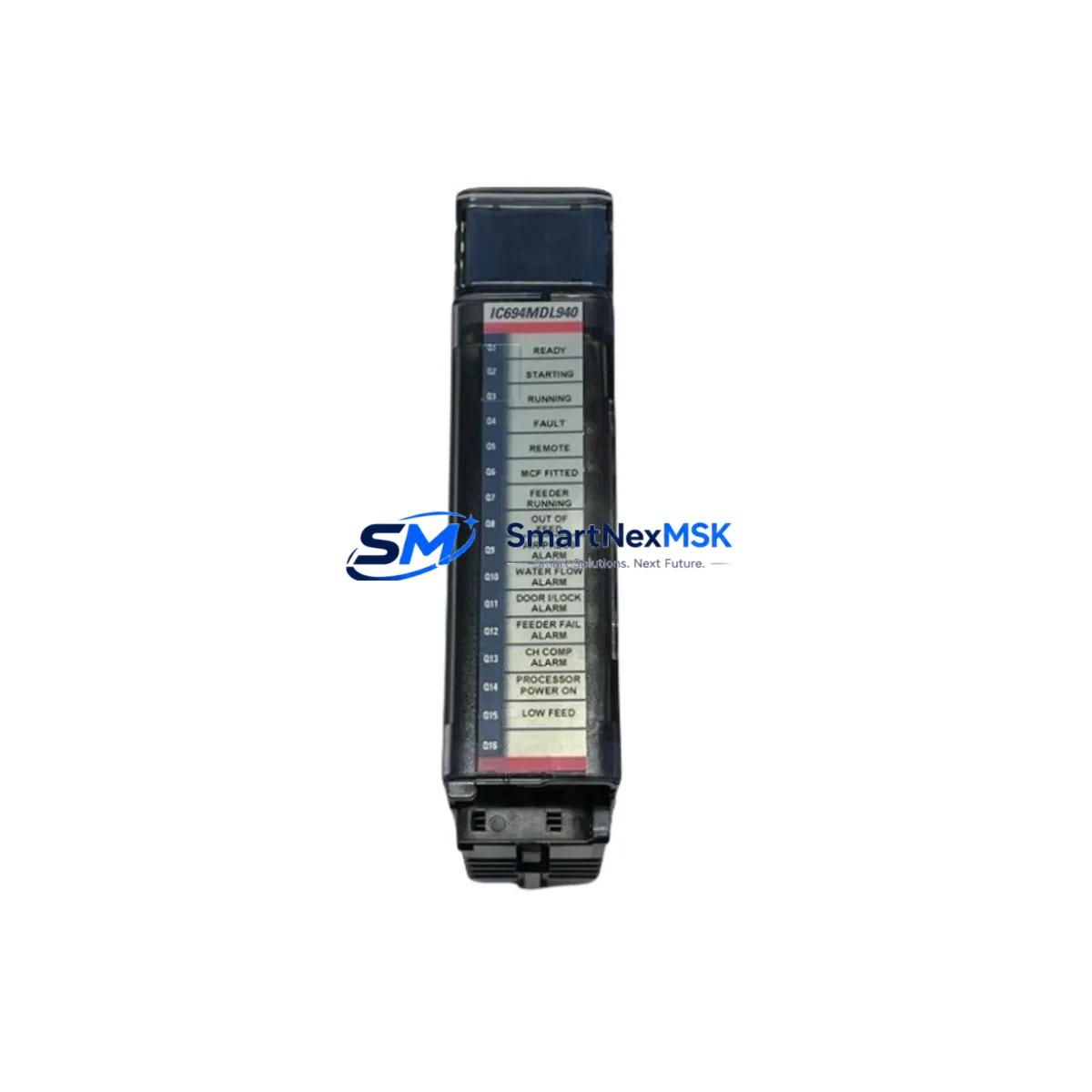
GE IC694MDL940F Maintenance-Ready Spare for Series 90-30 Automation
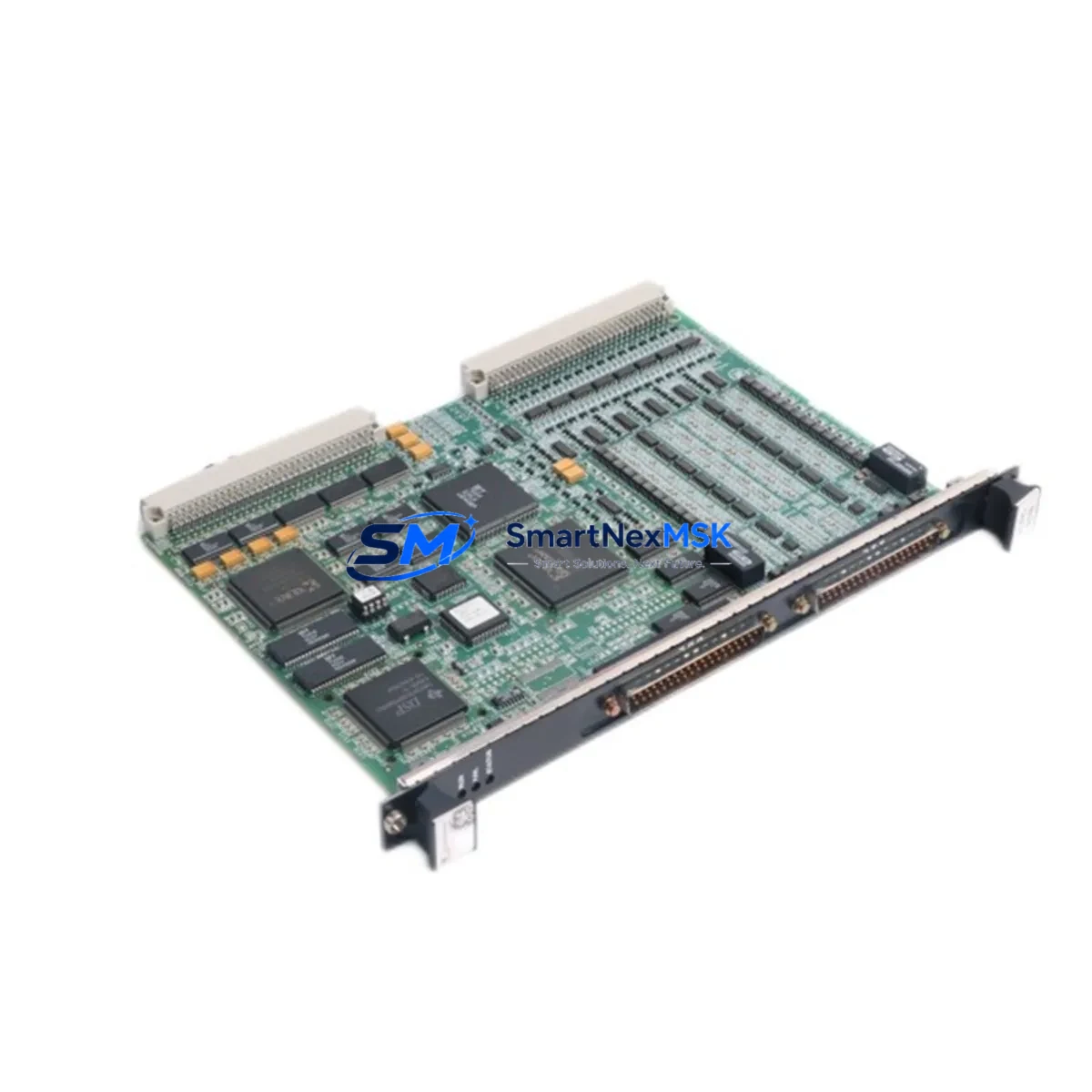
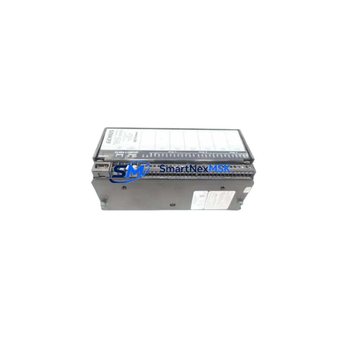
The GE IC694MDL940F is a 16-point relay output module engineered for the GE Series 90-30 programmable logic controller platform — one of the most widely deployed PLC families in discrete manufacturing, utilities, and process automation. As a maintenance-ready original spare, the IC694MDL940F is a direct replacement for aging or failed relay output modules in active production environments where unplanned downtime carries significant operational cost. Whether you are executing a planned shutdown, responding to an emergency fault, or building a strategic spare parts inventory, this module delivers verified compatibility, tested performance, and a 12-month warranty backed by pre-shipment inspection.
Spare Maintenance Table
| Parameter | Specification |
|---|---|
| Part Number | IC694MDL940F |
| Brand | GE (General Electric Automation) |
| Series | Series 90-30 (90-30 PLC) |
| Module Type | 16-Point Relay Output Module |
| Output Type | Relay (dry contact) |
| Output Points | 16 |
| Output Voltage Range | 5–250 VAC / 5–30 VDC |
| Max Load per Point | 2A resistive (AC/DC) |
| Isolation | Optical isolation, relay contact output |
| Backplane Compatibility | IC694CHS392, IC694CHS398, IC694CHS782 (5-slot, 10-slot, 14-slot) |
| CPU Compatibility | IC693CPU374, IC694CPU310, IC694CPU315, IC694CPU350, IC694CPU364 |
| Operating Temperature | 0°C to 60°C |
| Relative Humidity | 5–95% non-condensing |
| Mounting | Backplane slot insertion, no tools required |
| Condition | Original spare, pre-shipment tested |
| Warranty | 12 months from date of shipment |
| Lead Time | Ships within 1–3 business days |
| Origin | United States |
Maintenance Planning for Continuous Operation
When a relay output module such as the IC694MDL940F fails or shows signs of degradation — intermittent output, contact welding, or coil drive faults — the replacement process should be treated as a system-level maintenance event, not an isolated component swap. Maintenance engineers working on Series 90-30 control cabinets should simultaneously inspect the following components to prevent cascading failures and ensure the restored system operates reliably:
The IC694PWR321 or IC694PWR330 power supply module should be verified for output voltage stability and ripple, as relay coil drive faults are frequently caused by marginal power supply performance rather than the output module itself. The IC694MDL654 or IC694MDL660 discrete input modules sharing the same backplane should be checked for input signal integrity, particularly if the fault condition involved feedback loops or interlock logic. The IC694CHS392 or IC694CHS782 backplane chassis should be inspected for bent connector pins, corrosion, or mechanical damage at the module slot.
For systems using IC694CMM321 or IC694CMM302 communications modules, verify that the CPU-to-module communication path remains intact after the relay module replacement, especially in redundant or networked configurations. If the control cabinet includes IC694ALG220 or IC694ALG232 analog input modules, confirm that analog signal references and common grounds have not been disturbed during the maintenance intervention. Terminal blocks and field wiring connected to the relay output module — particularly those using IC694TBB032 or equivalent terminal board assemblies — should be inspected for loose terminations, insulation damage, and correct torque on screw terminals.
In facilities running legacy Series 90-30 systems alongside newer PACSystems hardware, it is common practice to maintain a cross-compatible spare parts kit that includes relay output modules, power supplies, CPU modules, and communication cards. Procurement engineers should note that the IC694MDL940F is compatible across multiple Series 90-30 chassis configurations, making it a high-value, multi-application spare that reduces the total number of unique SKUs required in the maintenance inventory. For sites managing planned obsolescence, pairing this module with a documented replacement strategy for the IC693MDL940 (the earlier Series 90-30 relay output variant) ensures continuity during system life extension programs.
Site Replacement Workflow
Step 1 — Isolate and de-energize: Follow site LOTO (Lockout/Tagout) procedures. De-energize the field load circuits connected to the relay output module. Do not rely solely on the PLC program to disable outputs — physically isolate field power at the appropriate disconnect.
Step 2 — Document current configuration: Before removing the IC694MDL940F, record the slot address, I/O map assignment, and any module-specific configuration parameters stored in the CPU (IC694CPU310 or equivalent). Use the programming software (Proficy Machine Edition or equivalent) to export the current hardware configuration file.
Step 3 — Remove the failed module: Release the module locking tab, slide the IC694MDL940F out of the backplane slot, and inspect the backplane connector for damage. Label the removed module with the fault date and symptom for traceability.
Step 4 — Install the replacement module: Insert the new IC694MDL940F into the same slot. Confirm the module seats fully and the locking tab engages. Reconnect field wiring to the terminal board, verifying wire assignments against the original documentation.
Step 5 — Power-up and verify: Restore power to the backplane. Confirm the CPU recognizes the module without hardware fault codes. Execute a forced output test on each of the 16 relay points to verify contact operation before returning the system to automatic mode.
Step 6 — Update maintenance records: Log the replacement in the site CMMS (Computerized Maintenance Management System), including the new module serial number, installation date, and warranty expiry (12 months from shipment date).
Spare Parts Support FAQ
Q1: Is the IC694MDL940F compatible with all Series 90-30 backplane configurations?
The IC694MDL940F is compatible with the standard Series 90-30 5-slot, 10-slot, and 14-slot backplanes (IC694CHS392, IC694CHS398, IC694CHS782). It is not compatible with Series 90-70 or PACSystems RX3i backplanes. Always verify the target chassis model before ordering.
Q2: What pre-shipment testing is performed on this module?
Each IC694MDL940F unit undergoes functional relay contact testing, isolation verification, and visual inspection prior to shipment. A test report is available upon request. The 12-month warranty covers manufacturing defects and functional failures under normal operating conditions.
Q3: Can this module replace the earlier IC693MDL940 variant?
The IC694MDL940F is the direct successor to the IC693MDL940 in the Series 90-30 product line. In most applications, it is a drop-in replacement. However, engineers should verify the hardware configuration file in the CPU to confirm the module type is correctly mapped, as some older CPU firmware versions may require a configuration update.
Q4: What is the recommended spare parts stocking strategy for Series 90-30 relay output modules?
For production-critical systems, a minimum of one IC694MDL940F per active chassis is recommended as on-site hot spare inventory. For multi-line facilities, a centralized spare parts pool covering relay output, discrete input, analog I/O, and power supply modules reduces mean time to repair (MTTR) and supports both planned and emergency maintenance scenarios.
© 2026 SMARTNEXMSK. All rights reserved.
Original Source: https://smartnexmsk.com
Contact: [email protected] | +86 18259474341