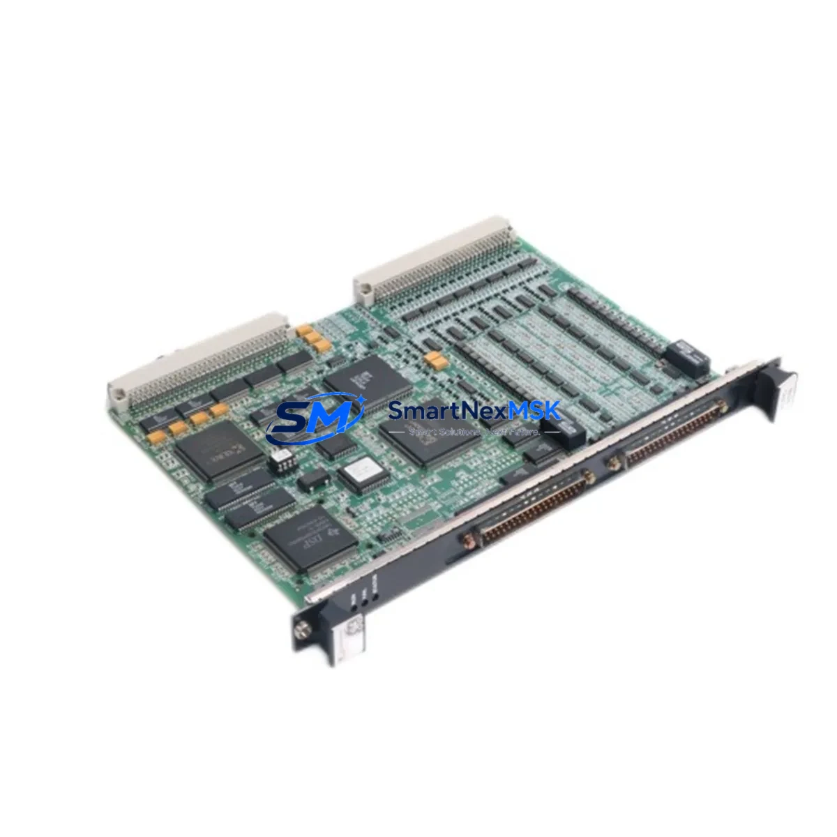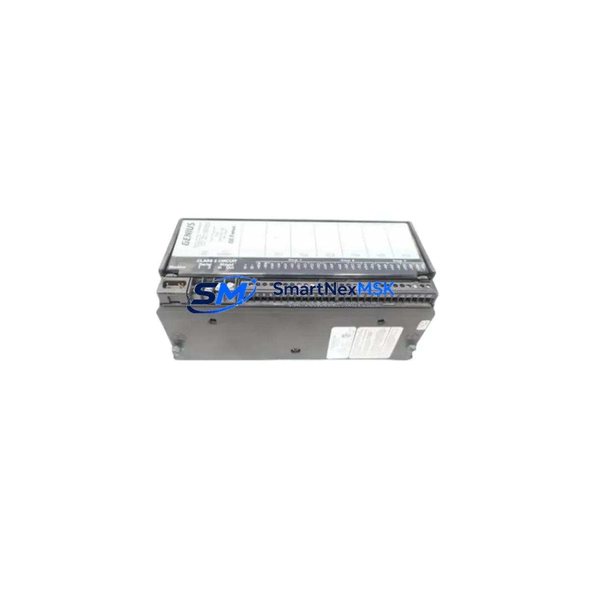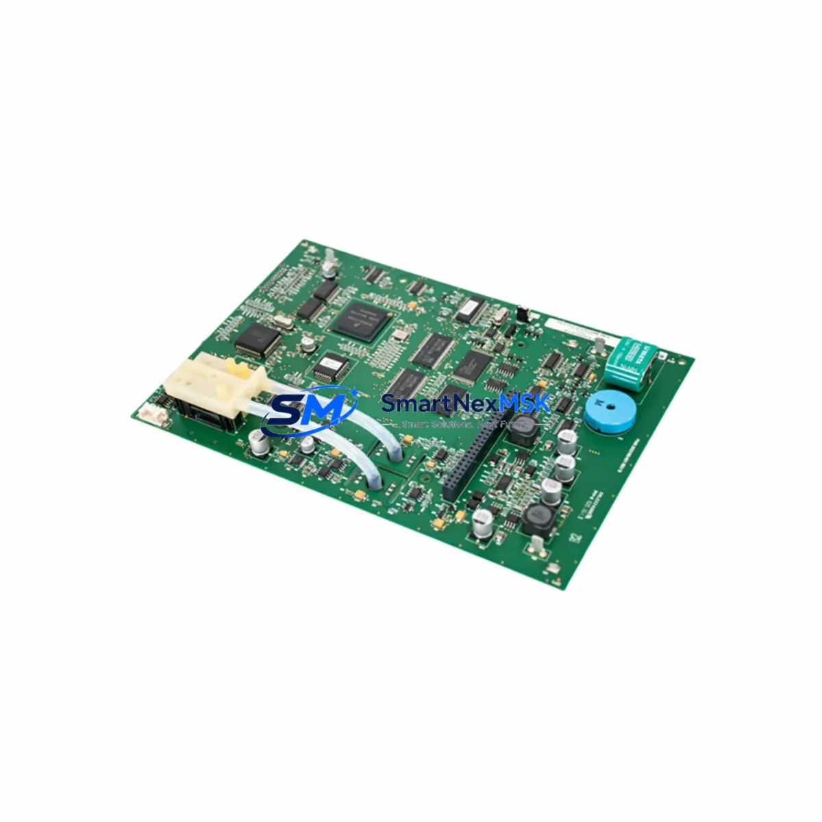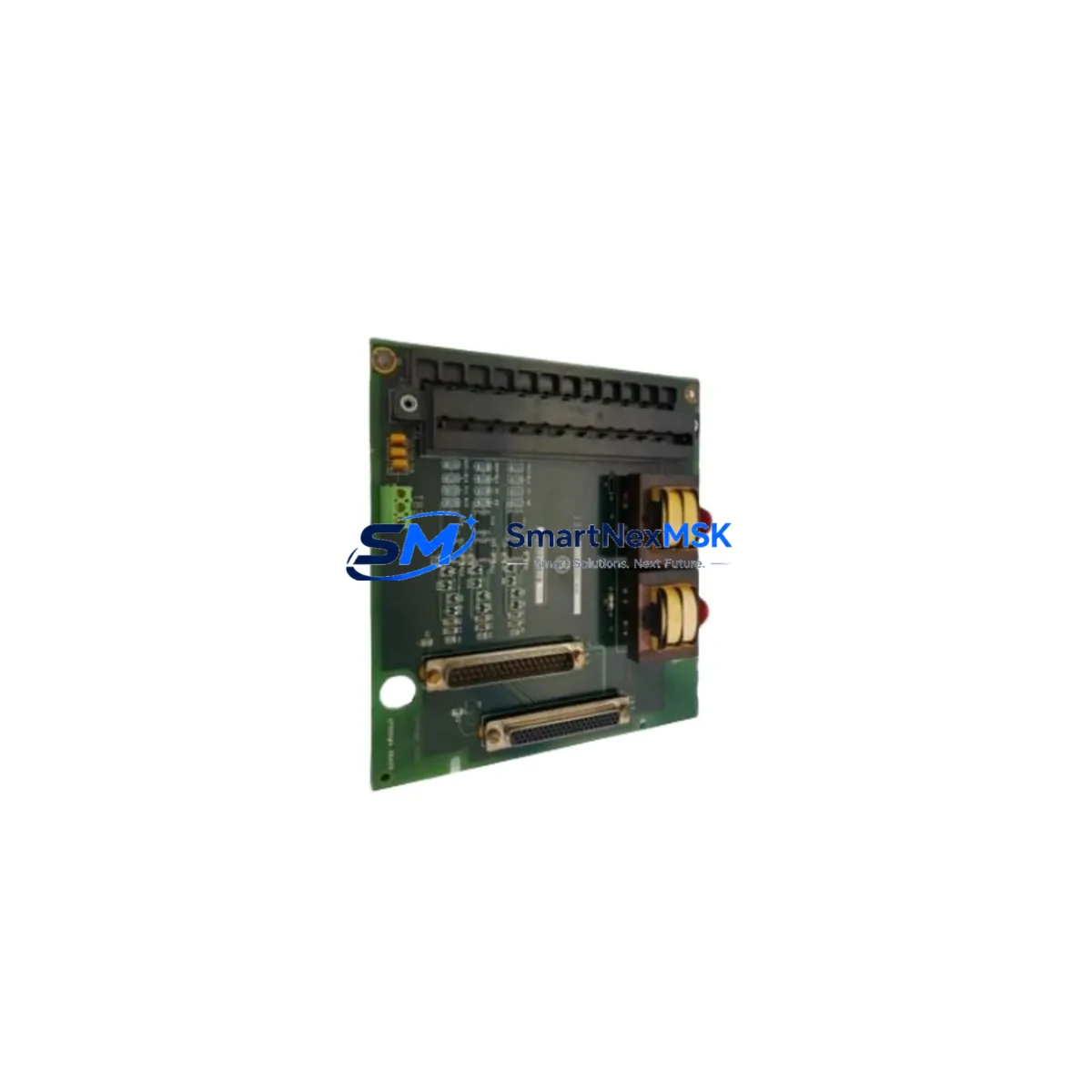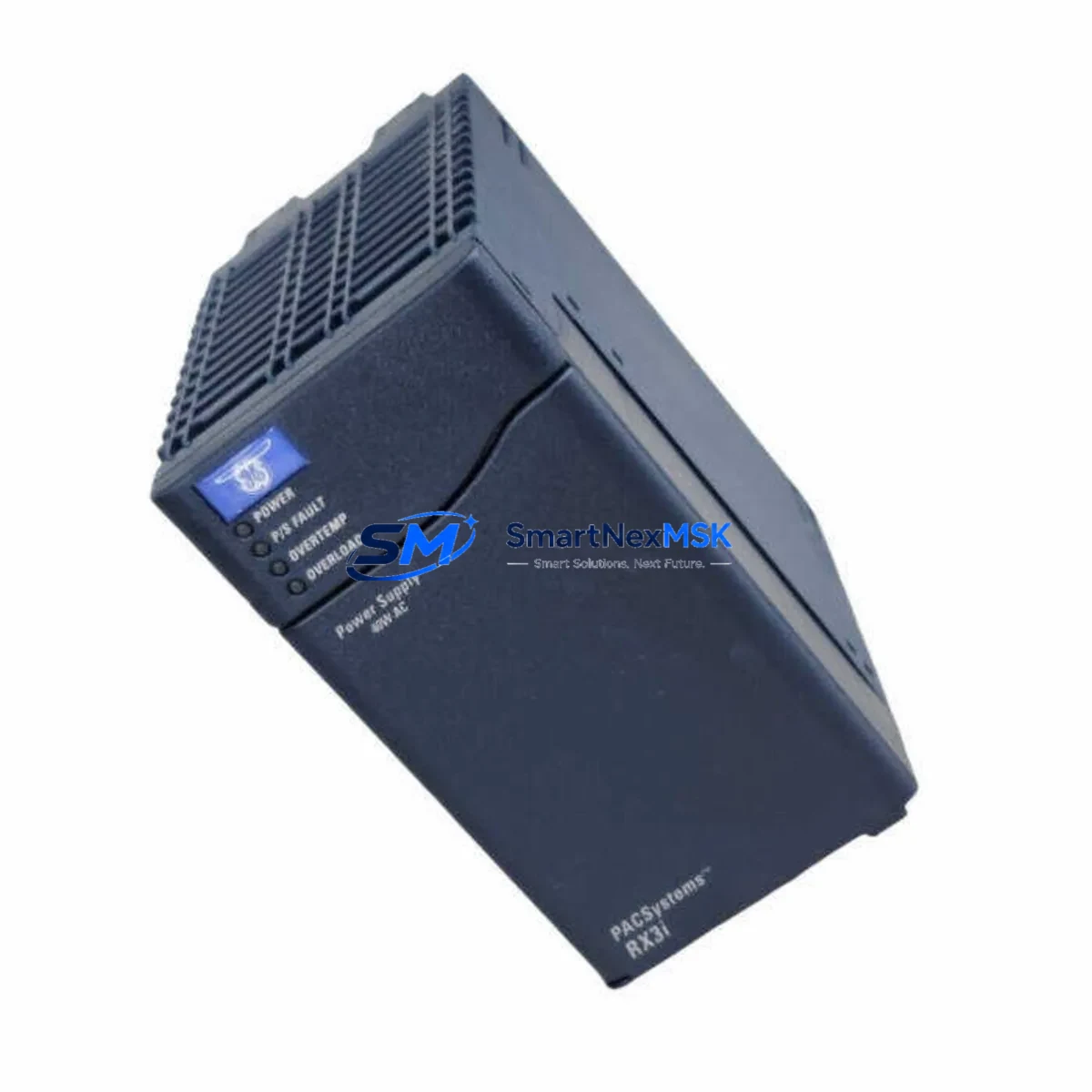
GE IC695PSA140 Retrofit-Ready 140W AC Supply for RX3i Systems
The GE IC695PSA140 is a 140-watt AC input power supply module engineered for the GE PACSystems RX3i control platform. As legacy automation systems reach end-of-life and original GE Intelligent Platforms spare parts become increasingly scarce, the IC695PSA140 remains one of the most sought-after retrofit components for engineers tasked with keeping RX3i-based control cabinets operational. Whether you are replacing a failed unit on a running production line, upgrading an aging control system, or building a spare-parts inventory ahead of a planned shutdown, this module delivers the electrical performance and mechanical compatibility your retrofit project demands.
Designed to mount directly into the IC695CHS012 or IC695CHS016 universal backplane, the IC695PSA140 accepts a wide-range AC input (85–264 VAC, 47–63 Hz) and delivers regulated 3.3 V, 5 V, and 24 VDC backplane rails to power the CPU, I/O modules, and communication cards installed in the same rack. Its terminal block wiring layout is identical to earlier RX3i power supply variants, which means field wiring can be reconnected without re-termination in most retrofit scenarios — a critical advantage when downtime budgets are measured in minutes rather than hours.
Upgrade Compatibility Table
| Attribute | IC695PSA140 | Notes / Retrofit Guidance |
|---|---|---|
| Input Voltage | 85–264 VAC, 47–63 Hz | Universal range; no tap switching required |
| Output Power | 140 W total | Verify rack load budget before replacement |
| Backplane Compatibility | IC695CHS012 / IC695CHS016 | Direct drop-in; no adapter required |
| Terminal Wiring | Screw-terminal block (L, N, PE) | Existing field wiring reusable in most cases |
| Common Replaced Models | IC695PSA040, IC695PSD040 | Confirm output wattage upgrade path with load calc |
| CPU Compatibility | IC695CPE302, IC695CPE305, IC695CPE310 | No firmware change required for power supply swap |
| Communication Modules | IC695ETM001, IC695PBM300 | Powered via backplane; no separate supply needed |
| Installation Slot | Slot 0 (dedicated PSU slot) | Cannot be installed in standard I/O slots |
| Commissioning Tool | Proficy Machine Edition (PME) | No hardware configuration change for PSU swap |
| Warranty | 12 Months | Covers manufacturing defects; DOA exchange policy |
Retrofit Planning for Existing Automation Systems
A successful IC695PSA140 retrofit begins well before the module arrives on site. The first step is an accurate power budget audit of the existing rack. Engineers should enumerate every module currently installed — including the IC695CPE302 or IC695CPE305 CPU, any IC695ETM001 Ethernet communication modules, IC695ALG600 analog I/O modules, IC695MDL664 discrete output modules, and any IC695PBM300 PROFIBUS master cards — and sum their individual backplane current draws against the 140 W capacity of the IC695PSA140. If the existing rack was previously powered by the lower-rated IC695PSA040 or IC695PSD040, the upgrade to the IC695PSA140 provides additional headroom for I/O expansion without requiring a second power supply or a larger rack chassis.
Terminal wiring verification is the next critical checkpoint. The IC695PSA140 uses a removable screw-terminal block for AC line, neutral, and protective earth connections. In most retrofit scenarios the existing field wiring — typically 1.5 mm² or 2.5 mm² stranded copper — can be reconnected directly to the replacement module’s terminal block without re-pulling cables. Confirm conductor cross-section, torque specification (0.5–0.6 N·m), and the presence of a properly rated upstream circuit breaker (typically 10 A, curve C) before energizing.
Backplane seating and module address assignment require no configuration changes when swapping a like-for-like power supply. The IC695CHS012 or IC695CHS016 backplane recognizes the PSU by slot position, not by a software-assigned node address, so the replacement module is immediately recognized by the IC695CPE310 CPU upon power-up. If the retrofit involves migrating from a Series 90-70 rack to an RX3i universal backplane, engineers must account for the physical differences in the IC698CHS009 or IC698CHS017 Series 90-70 rack versus the RX3i IC695CHS016, and plan for re-termination of I/O wiring to the new terminal assemblies.
HMI screen validation is often overlooked during power supply retrofits. Although a PSU swap does not alter the PLC program or I/O map, a cold restart of the IC695CPE302 CPU will cause a brief interruption to the Ethernet link between the controller and any connected iFIX or CIMPLICITY SCADA station. Operators should be informed of the planned outage window, and HMI alarm suppression should be activated before the module is removed to prevent nuisance alarms from flooding the historian. After the IC695PSA140 is seated and powered, verify that all communication links — including the IC695ETM001 Ethernet module and any IC695PBM300 PROFIBUS connections — re-establish within the expected timeout period defined in the PME hardware configuration.
Downtime Control During System Migration
Minimizing unplanned downtime is the primary concern for any maintenance engineer performing a live-system power supply replacement. The recommended approach for IC695PSA140 retrofits is a planned, single-shift swap executed during a scheduled maintenance window. Before removing the failed or aging IC695PSA040, use Proficy Machine Edition to perform a full program backup of the IC695CPE302 or IC695CPE305 CPU to a local engineering workstation. Store the .mef project file and the associated hardware configuration export in a version-controlled directory so that the program can be restored within minutes if an unexpected fault occurs during the swap.
With the program backed up, de-energize the control cabinet following your site’s lockout/tagout (LOTO) procedure. Remove the AC terminal block from the existing power supply — the removable connector design of the IC695PSA140 means the field wiring block can be unplugged as a single assembly and re-inserted into the replacement module without disturbing individual conductor terminations. Seat the new IC695PSA140 firmly into Slot 0 of the IC695CHS016 backplane, re-attach the terminal block, and restore power. The RX3i CPU will execute its standard power-up diagnostic sequence, and if the program was stored in battery-backed RAM or flash memory, it will resume execution automatically without requiring a download from the engineering workstation. Total swap time for an experienced technician is typically 15–30 minutes, keeping the production impact well within a single shift’s maintenance window.
For systems where even a brief interruption is unacceptable, consider pre-staging a fully configured hot-standby rack using a second IC695CHS016 backplane populated with an IC695CPE310 CPU and a pre-loaded IC695PSA140, allowing a rack-level swap that further compresses the outage window. All modules sourced from SMARTNEXMSK are pre-tested prior to shipment and covered by a 12-month warranty, reducing the risk of a DOA unit extending your downtime beyond the planned window.
Retrofit Support FAQ
Q1: Is the IC695PSA140 a direct drop-in replacement for the IC695PSA040?
Yes. The IC695PSA140 occupies the same Slot 0 position in the IC695CHS012 and IC695CHS016 backplanes and uses the same removable AC terminal block layout as the IC695PSA040. The primary difference is output wattage — 140 W versus 40 W — which provides additional capacity for expanded I/O configurations. No changes to the PME hardware configuration file are required for a like-for-like slot swap.
Q2: What commissioning checks are required after installing the IC695PSA140?
After seating the module and restoring AC power, verify the green PWR LED on the IC695PSA140 front panel illuminates steadily. Confirm the IC695CPE302 or IC695CPE310 CPU transitions to RUN mode and that all I/O modules — including any IC695MDL664 discrete output or IC695ALG600 analog input cards — report healthy status in the PME I/O diagnostics view. Re-establish and verify all Ethernet and PROFIBUS communication links before releasing the system to production.
Q3: How do I verify wiring compatibility before the replacement module arrives?
Download the IC695PSA140 Installation Manual (GFK-2314) from the GE Automation documentation archive and compare the terminal block pinout and conductor cross-section specifications against your existing field wiring. In most installations using standard 1.5–2.5 mm² stranded copper with ferrule terminations, the existing wiring is fully compatible. Confirm upstream overcurrent protection is rated at 10 A (curve C) or per your local electrical code.
Q4: What does the 12-month warranty cover, and what is the exchange process?
All IC695PSA140 modules supplied by SMARTNEXMSK carry a 12-month warranty covering manufacturing defects and functional failures under normal operating conditions. If a module is found to be defective on arrival (DOA) or fails within the warranty period, contact [email protected] with your order number and a description of the fault. We will arrange a priority replacement shipment to minimize your downtime exposure. Warranty does not cover damage resulting from incorrect installation, overvoltage events, or physical mishandling.
© 2026 SMARTNEXMSK. All rights reserved.
Original Source: https://smartnexmsk.com
Contact: [email protected] | +86 18259474341