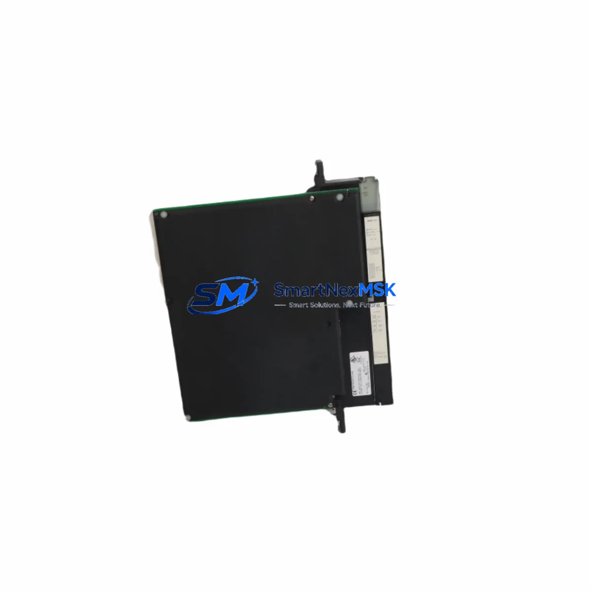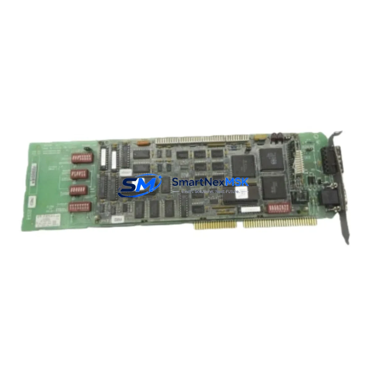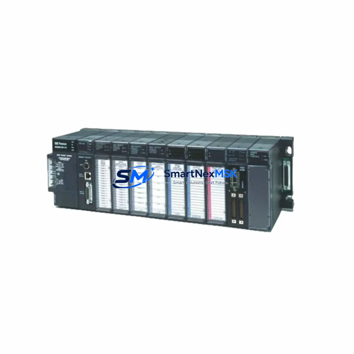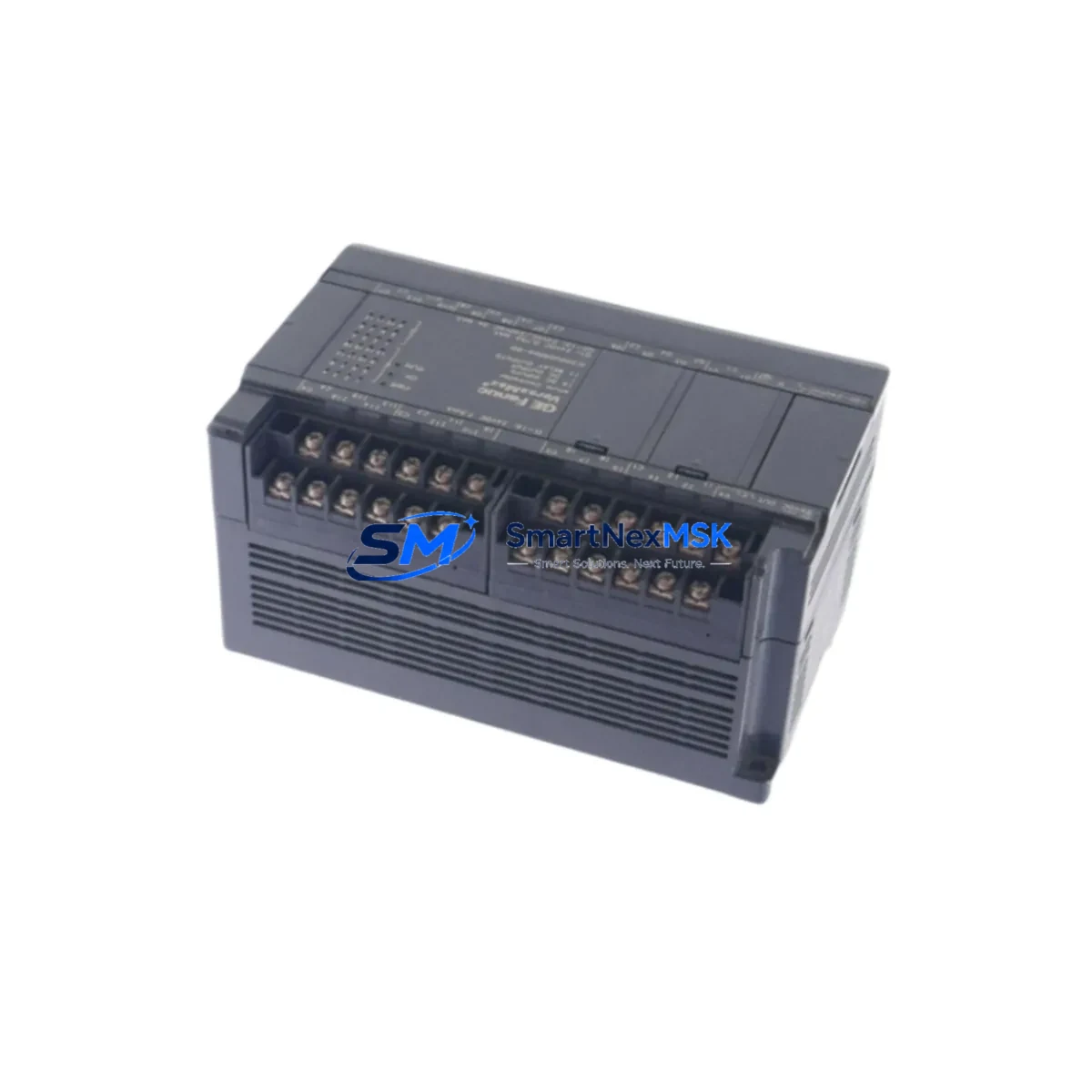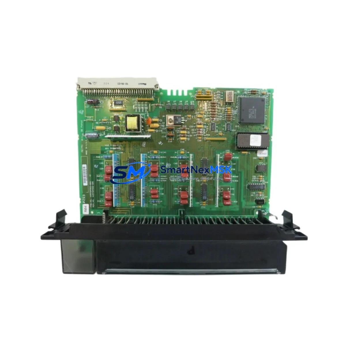
GE IC697ALG440 Retrofit-Ready Analog Output for Series 90-70 Control Systems
The GE Fanuc IC697ALG440 is a 4-channel analog current output module designed for the Series 90-70 PLC platform. As legacy GE Series 90-70 systems approach end-of-life and original spare parts become increasingly scarce, the IC697ALG440 remains one of the most sought-after retrofit components for engineers tasked with keeping aging control architectures operational. Whether you are replacing a failed output card in a continuous process line, upgrading a control cabinet to extend its service life, or migrating I/O capacity to support expanded production, this module delivers the signal fidelity and rack compatibility that Series 90-70 installations demand.
Each IC697ALG440 provides 4 isolated analog current outputs in the 4–20 mA range, with 12-bit resolution and individual channel diagnostics. The module seats directly into any Series 90-70 rack — including the IC697CHS750, IC697CHS782, and IC697CHS790 baseplate configurations — without mechanical modification. Terminal block wiring follows the standard Series 90-70 pinout, meaning field cables from a decommissioned or failed module can be reconnected without rewiring the marshalling panel.
Upgrade Compatibility Table
| Parameter | IC697ALG440 Specification | Retrofit Notes |
|---|---|---|
| Output Channels | 4 × Analog Current (4–20 mA) | Direct replacement for same-channel-count legacy cards |
| Resolution | 12-bit | Compatible with existing PLC program scaling blocks |
| Rack Compatibility | IC697CHS750 / IC697CHS782 / IC697CHS790 | No rack modification required; any Series 90-70 slot |
| Backplane Interface | Series 90-70 VME-style backplane | Module address set via software; no DIP switch changes |
| Power Consumption | ≤ 1.5 A @ 5 VDC from backplane | Verify IC697PWR711 or IC697PWR724 PSU headroom before installation |
| Communication Protocol | Series 90-70 internal I/O bus | No protocol migration required; compatible with IC697CMM742 and IC697CMM711 comm modules |
| Terminal Block | Standard Series 90-70 removable terminal block | Field wiring transfers directly; no re-termination needed |
| Programming Compatibility | Logicmaster 90-70 / Proficy Machine Edition | Existing analog output blocks (%AQ) remain valid; no program rewrite |
| HMI Integration | Tag-based via CPU data table | iFIX, CIMPLICITY, and third-party SCADA tags remain unchanged |
| Warranty | 12 Months | Covers manufacturing defects; includes pre-shipment functional test |
Retrofit Planning for Existing Automation Systems
Successful integration of the IC697ALG440 into an existing Series 90-70 control system begins with a thorough pre-installation audit. Engineers should first confirm that the host rack’s power supply — typically an IC697PWR711 (35 W) or IC697PWR724 (55 W) — has sufficient current headroom to support the replacement module alongside all other installed cards, including any IC697MDL340 discrete output modules, IC697ALG320 analog input modules, and IC697BEM731 Bus Expansion Modules already drawing from the same backplane.
Terminal block wiring is one of the most time-sensitive steps in a live-system retrofit. Because the IC697ALG440 uses the same removable terminal block format as other Series 90-70 I/O modules, field cables can be transferred directly from the failed card to the replacement without disturbing marshalling panel connections. Before removal, photograph or document the existing wiring layout and verify loop continuity on each 4–20 mA output channel using a calibrated loop calibrator. This step is especially important when the module drives control valves, variable-frequency drives, or positioners that must maintain a defined output state during the changeover window.
Module addressing in the Series 90-70 architecture is software-defined through the hardware configuration tool in Logicmaster 90-70 or Proficy Machine Edition. When inserting the IC697ALG440 into the same rack slot previously occupied by the failed module, the CPU — typically an IC697CPU772 or IC697CPU781 — will recognize the replacement automatically on the next power cycle, provided the hardware configuration file has not been altered. If the slot assignment has changed, update the I/O configuration in the programming software and download the revised hardware configuration to the controller before re-enabling outputs.
For systems that also incorporate an IC697CMM742 Ethernet Interface Module or an IC697CMM711 Communications Control Module, verify that the communication link between the CPU and any upstream SCADA or DCS host remains active throughout the module swap. In most cases, the communications modules operate independently of the I/O backplane and will continue passing data during a single-slot module replacement, minimizing disruption to supervisory control layers.
Where the retrofit involves expanding I/O capacity rather than a direct one-for-one replacement, engineers may also need to evaluate the IC697CHS790 9-slot expansion rack and the IC697BEM731 Bus Expansion Module to accommodate additional analog output channels without replacing the main CPU rack. This approach preserves the existing program logic and HMI tag structure while adding the output capacity required by modernized process equipment.
Downtime Control During System Migration
Minimizing unplanned downtime is the primary concern in any Series 90-70 retrofit project. The IC697ALG440 supports a controlled hot-swap procedure in systems where the rack power can be isolated at the slot level — confirm this capability against your specific rack revision before proceeding. In systems where full rack power-down is required, coordinate the replacement window with production scheduling to align with planned maintenance intervals.
Before powering down, use Proficy Machine Edition or Logicmaster 90-70 to place all analog output channels in a defined safe state — typically 4 mA (0%) or a process-specific hold value — to prevent uncontrolled actuator movement during the changeover. Save a backup of the current hardware configuration and program logic to an offline storage location. This backup serves as the recovery baseline if the replacement module requires a configuration adjustment.
After installing the IC697ALG440 and restoring rack power, perform a channel-by-channel output verification using a calibrated milliamp meter before reconnecting field devices. Confirm that each channel responds correctly to forced output commands from the programming terminal, then release the outputs to program control and monitor the first several scan cycles for any fault diagnostics reported by the CPU. Most Series 90-70 installations complete this verification sequence in under 30 minutes, keeping total planned downtime well within a single maintenance shift.
For critical continuous-process applications where even brief output interruptions are unacceptable, consider staging a pre-configured spare IC697ALG440 with the hardware configuration already loaded and outputs pre-verified on a bench test rack before the scheduled maintenance window. This approach reduces in-field installation time to the physical swap and wiring transfer only, typically under 10 minutes.
Retrofit Support FAQ
Q: Is the IC697ALG440 a direct drop-in replacement for other Series 90-70 analog output modules?
A: Yes. The IC697ALG440 is mechanically and electrically compatible with all Series 90-70 rack slots. It replaces earlier 4-channel analog current output cards without requiring rack modification, wiring changes, or program rewrites, provided the replacement module is configured to the same slot address in the hardware configuration file.
Q: Will my existing PLC program and HMI screens work without modification after installing the IC697ALG440?
A: In a direct slot-for-slot replacement, no program changes are required. The CPU continues to address the module through the same %AQ reference addresses, and SCADA or HMI systems connected via the IC697CMM742 or similar communications modules will see no change in tag mapping. If the slot assignment changes, a hardware configuration update and download are required, but the ladder logic and HMI screens remain unaffected.
Q: What pre-shipment testing is performed on each IC697ALG440 unit?
A: Every IC697ALG440 shipped by SMARTNEXMSK undergoes a functional output test across all 4 channels at 4 mA, 12 mA, and 20 mA setpoints, a backplane connector inspection, and a firmware revision verification before packaging. Units are shipped with a test record and are covered by a 12-month warranty against manufacturing defects from the date of delivery.
Q: What should I verify regarding power supply capacity before installing the IC697ALG440?
A: Confirm that the installed power supply — IC697PWR711 or IC697PWR724 — has at least 1.5 A of available 5 VDC headroom after accounting for all other modules in the rack. If the rack is fully populated and the power supply is operating near its rated capacity, consider redistributing modules across an expansion rack using the IC697BEM731 Bus Expansion Module, or upgrading to the higher-capacity IC697PWR724 supply before adding the replacement module.
© 2026 SMARTNEXMSK. All rights reserved.
Original Source: https://smartnexmsk.com
Contact: [email protected] | +86 18259474341