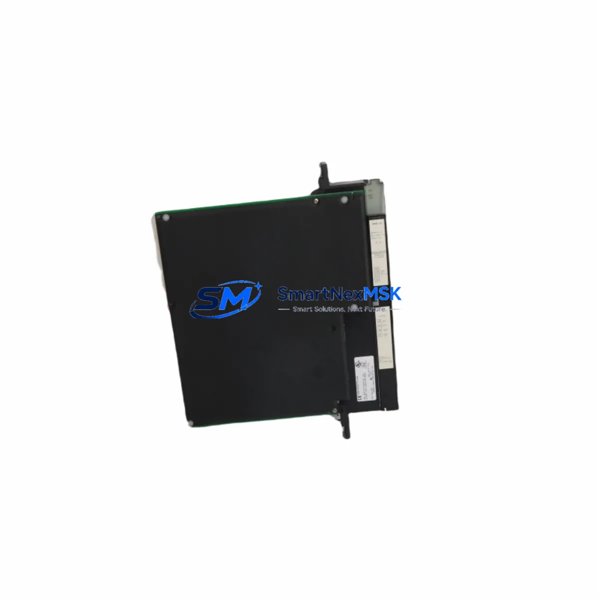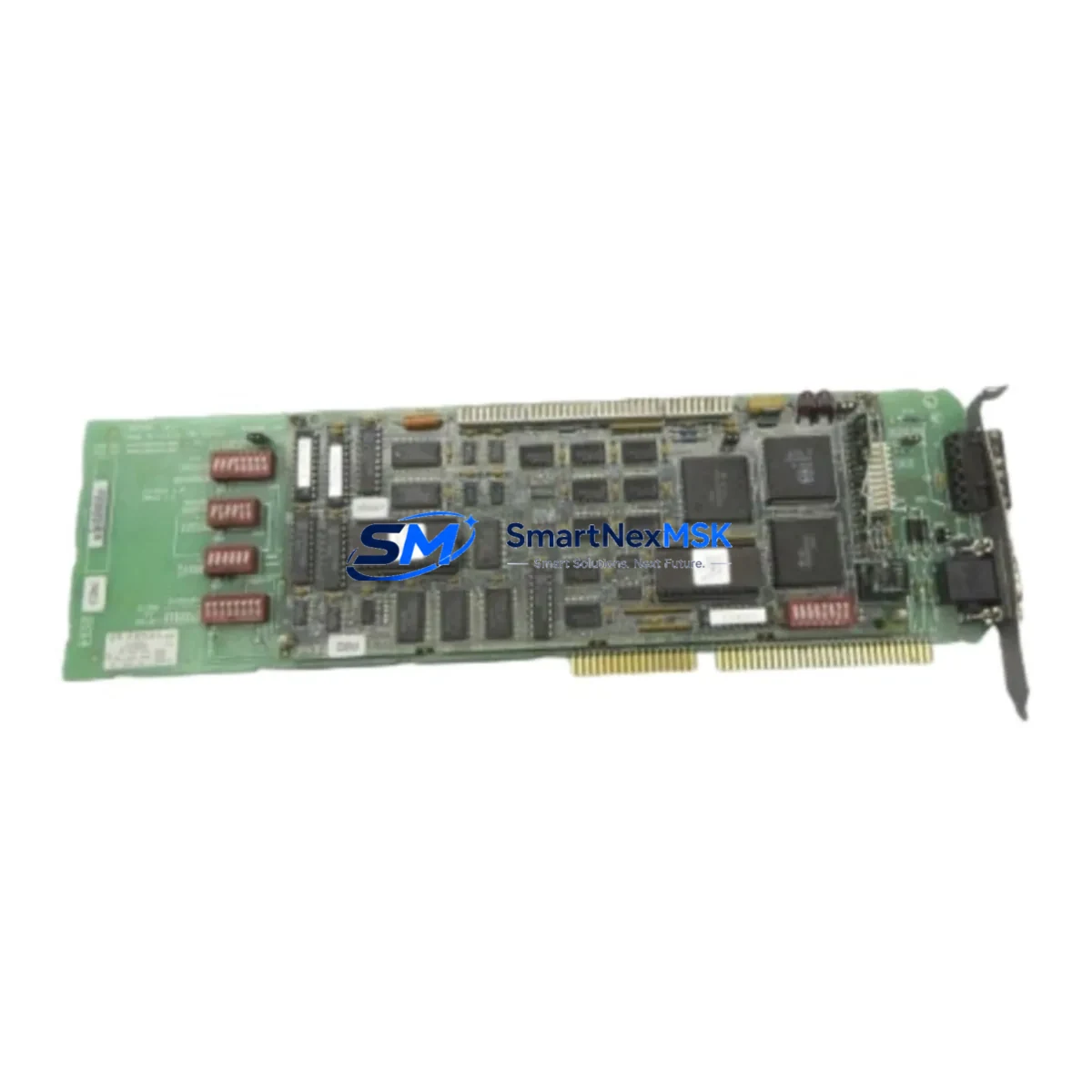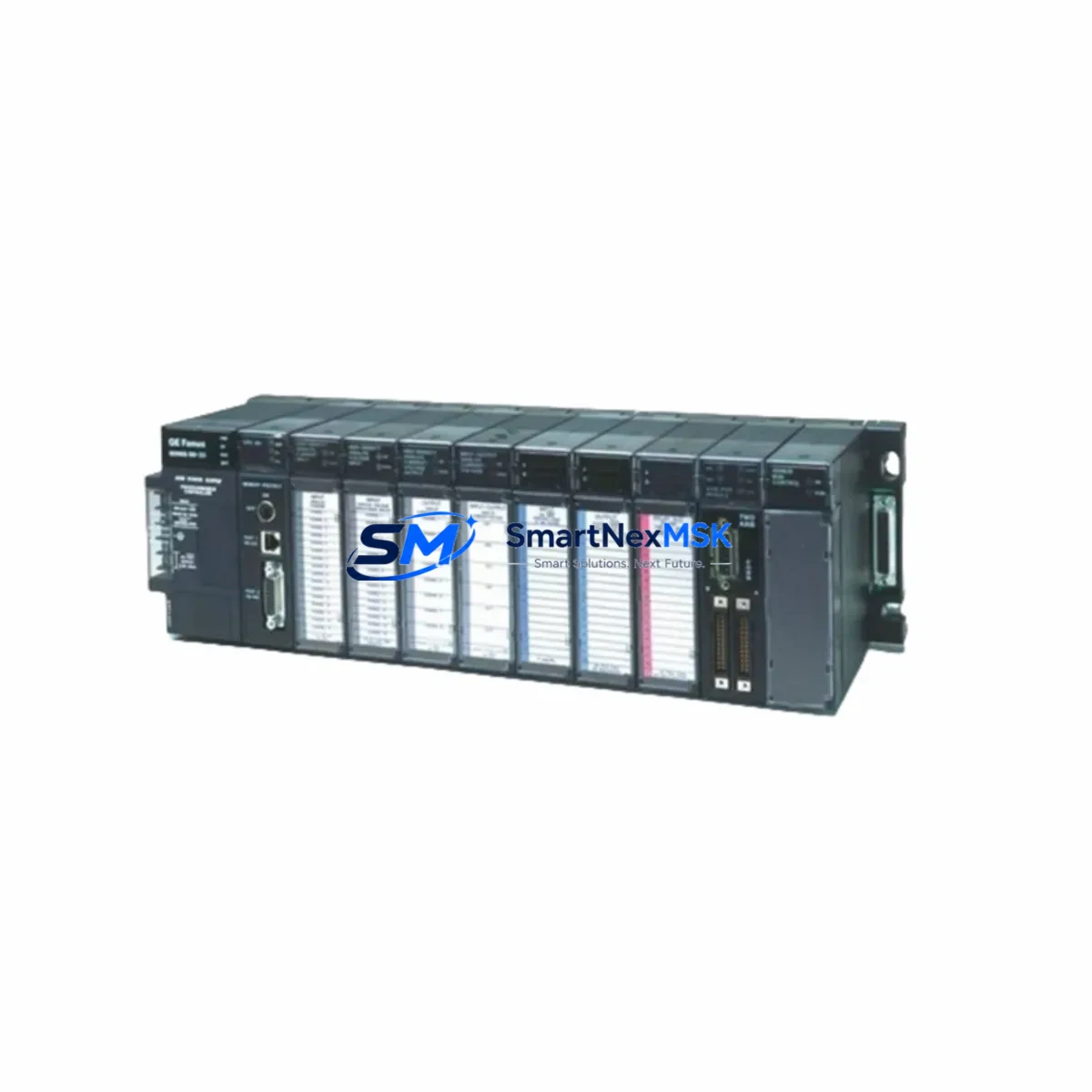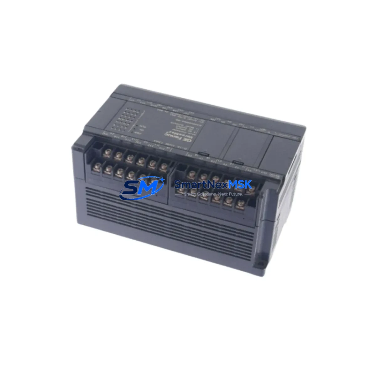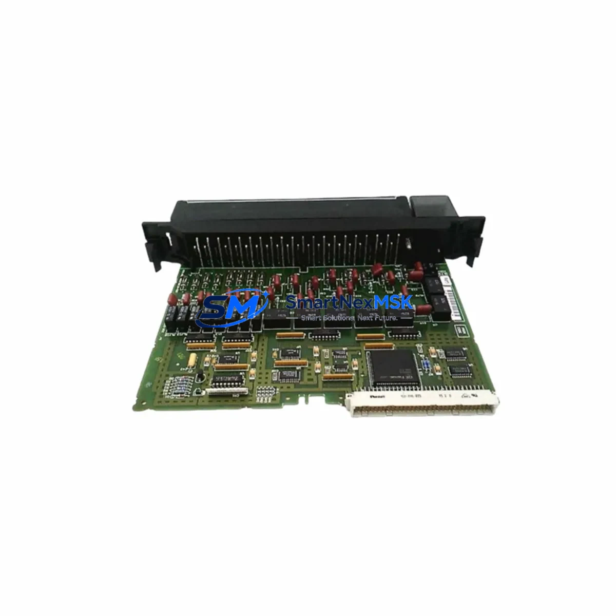
GE IC697MDL940 Maintenance-Ready Spare for Series 90-70 Automation
The GE Fanuc IC697MDL940 is a discrete output module designed for the Series 90-70 programmable logic controller platform — one of the most widely deployed industrial automation architectures in process manufacturing, power generation, and heavy industry. As original equipment reaches end-of-life and OEM support windows close, maintaining a verified spare of the IC697MDL940 becomes a critical element of any plant-level downtime prevention strategy.
This listing provides a maintenance-ready, original IC697MDL940 output module, pre-tested before shipment, backed by a 12-month warranty, and available for fast dispatch to minimize unplanned production stoppages. Whether you are managing a scheduled turnaround, responding to an emergency fault, or building out your control room spare parts inventory, this module is sourced and verified to meet the original GE Fanuc specification.
Spare Maintenance Table
| Parameter | Specification |
|---|---|
| Part Number | IC697MDL940 |
| Brand | GE Fanuc |
| Series | Series 90-70 |
| Module Type | Discrete Output Module |
| Output Points | 16 Points (Relay) |
| Output Voltage Range | 5–250V AC/DC |
| Output Current per Point | 2A (resistive load) |
| Backplane Compatibility | IC697CHS750, IC697CHS782, IC697CHS790 (Series 90-70 racks) |
| Isolation | Optical isolation between field and logic side |
| Operating Temperature | 0°C to 60°C |
| Mounting | Series 90-70 backplane slot (any I/O slot) |
| Indicator LEDs | Per-channel output status LEDs |
| Application Environment | Industrial control panels, process automation, power distribution |
| Maintenance Recommendation | Inspect relay contacts annually; replace module if contact resistance exceeds threshold or intermittent faults are logged |
| Warranty | 12 Months |
| Condition | Original, pre-shipment tested |
Maintenance Planning for Continuous Operation
When replacing or inspecting the IC697MDL940 in a Series 90-70 control cabinet, a thorough maintenance engineer will not stop at the output module itself. The IC697MDL940 drives field devices through relay contacts, meaning the surrounding electrical circuit must be evaluated in parallel to ensure the replacement restores full system integrity.
Begin with the IC697PWR710 or IC697PWR711 power supply module — verify output voltage rails are within tolerance before inserting the new output module. A degraded power supply is a common root cause of repeated output module failures and is frequently overlooked during emergency replacements. Next, inspect the IC697MDL340 or IC697MDL341 discrete input modules in the same rack; input signal integrity must be confirmed to validate that the PLC program is receiving correct feedback after the output module swap.
Check the IC697CPU772 or IC697CPU781 CPU module for any latched fault codes related to the failed output slot — clear diagnostics only after the replacement module has been seated and verified. For systems using IC697BEM711 or IC697BEM713 bus expansion modules, confirm that rack-to-rack communication is stable and that no I/O scan errors are present on the expanded rack containing the IC697MDL940.
Terminal blocks and field wiring connected to the IC697MDL940’s output terminals should be inspected for loose connections, oxidized contacts, and insulation degradation — particularly in high-cycle or high-temperature environments. If the system uses IC697MDL653 or IC697MDL654 analog output modules in adjacent slots, verify that the backplane connector seating is undisturbed after the discrete output module replacement.
For facilities running legacy GENIUS bus architectures, the IC697BEM731 GENIUS Bus Controller should be checked for communication health after any rack-level maintenance. Additionally, if the control system interfaces with an IC697CMM711 or IC697CMM742 communications module, confirm that network connectivity and I/O mapping remain intact post-replacement. Maintaining a documented spare parts list that includes the IC697MDL940 alongside these associated modules ensures that your maintenance team can execute a complete cabinet restoration without secondary delays caused by missing components.
Site Replacement Workflow
Step 1 — Fault Isolation: Identify the failed slot using the Series 90-70 CPU fault table or the Logicmaster/Proficy ME programmer. Note the slot address and rack number before powering down the affected rack section.
Step 2 — Safe Isolation: De-energize field circuits connected to the IC697MDL940 output terminals. Follow your site LOTO (Lockout/Tagout) procedure. Do not remove the module under live field voltage.
Step 3 — Module Removal: Release the module locking tab, slide the IC697MDL940 out of the backplane slot, and inspect the backplane connector for damage or contamination before inserting the replacement.
Step 4 — Replacement Insertion: Seat the new IC697MDL940 firmly into the same slot. The module is hot-swap capable on supported CPU firmware versions — verify your firmware revision before attempting live insertion.
Step 5 — Configuration Verification: Power up the rack and confirm the CPU recognizes the replacement module without configuration mismatch faults. If a mismatch is reported, use Logicmaster 90 or Proficy Machine Edition to update the hardware configuration and download to the CPU.
Step 6 — Functional Test: Force each output point individually from the programmer to verify relay operation and field device response before returning the system to automatic mode.
Step 7 — Documentation: Record the replacement date, module serial number, and post-replacement test results in your maintenance management system (CMMS). Update your spare parts inventory to trigger reorder of the consumed IC697MDL940 spare.
Spare Parts Support FAQ
Q1: Is this IC697MDL940 an original GE Fanuc module or a third-party replacement?
This is an original GE Fanuc IC697MDL940 module. We do not supply counterfeit, rebranded, or third-party substitute modules. Each unit is individually tested before shipment to verify relay contact integrity, backplane communication, and LED indicator function.
Q2: What is the warranty coverage and how does it apply to field-installed modules?
All IC697MDL940 modules supplied by SMARTNEXMSK carry a 12-month warranty from the date of shipment. The warranty covers manufacturing defects and verified functional failures under normal operating conditions. It does not cover damage resulting from incorrect installation, overvoltage events, or physical mishandling. Warranty claims are processed with return shipping support.
Q3: Can this module replace older IC697MDL940 revisions already installed in my system?
Yes. The IC697MDL940 has maintained backward hardware compatibility across its production revisions. The replacement module will seat in any Series 90-70 rack slot previously occupied by an earlier IC697MDL940 revision without requiring configuration changes in most cases. If your CPU firmware is below a certain revision, a configuration download may be required — contact our technical team with your CPU part number for confirmation.
Q4: How quickly can this module be shipped, and do you support emergency orders?
Standard orders are processed and dispatched within 1–2 business days. For emergency plant-down situations, contact us directly at [email protected] or +86 18259474341 to arrange priority dispatch. We maintain standing inventory of high-demand Series 90-70 spare modules to support unplanned maintenance events.
© 2026 SMARTNEXMSK. All rights reserved.
Original Source: https://smartnexmsk.com
Contact: [email protected] | +86 18259474341