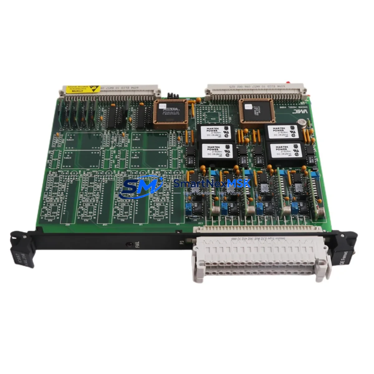
GE IC697VAL314 Maintenance-Ready Spare for Series 90-70 Automation
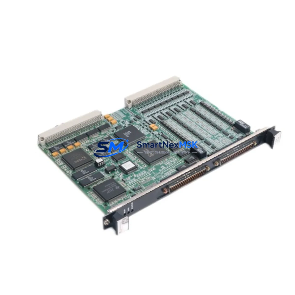
The GE IC697VAL314 is an original 8-channel analog output module designed for the GE Series 90-70 PLC platform — one of the most widely deployed distributed control architectures in heavy industry, power generation, water treatment, and process manufacturing. When this module fails or degrades, the consequences extend beyond a single I/O point: the entire analog output loop — including field instruments, control valves, and actuator feedback — is interrupted, triggering unplanned downtime and production loss. Sourcing a verified, tested replacement quickly is the single most effective action a maintenance team can take to restore normal operation.
At SMARTNEXMSK, every IC697VAL314 unit is inspected, functionally tested, and shipped with a 12-month warranty. We maintain standing inventory to support emergency replacement, planned maintenance shutdowns, and long-term spare parts programs for aging Series 90-70 installations.
Spare Maintenance Table
| Parameter | Specification |
|---|---|
| Part Number | IC697VAL314 |
| Brand | GE (General Electric Automation) |
| Series | Series 90-70 |
| Module Type | Analog Output Module |
| Output Channels | 8 Channels |
| Output Signal | 4–20 mA / 0–10 VDC (configurable per channel) |
| Resolution | 12-bit |
| Backplane Compatibility | IC697CHS750, IC697CHS782, IC697CHS790 (Series 90-70 racks) |
| CPU Compatibility | IC697CPU731, IC697CPU771, IC697CPU781, IC697CPU782 |
| Power Supply Requirement | Series 90-70 rack-mounted PSU (IC697PWR711 / IC697PWR724) |
| Operating Temperature | 0°C to 60°C |
| Mounting | Series 90-70 backplane slot (any I/O slot) |
| Application Environment | Industrial process control, DCS integration, SCADA-driven loops |
| Condition | Original, tested, fully functional |
| Warranty | 12 Months |
Maintenance Planning for Continuous Operation
Replacing the IC697VAL314 in a live Series 90-70 system is rarely an isolated task. Experienced maintenance engineers know that analog output failures are often symptomatic of broader electrical stress in the control cabinet. Before returning the system to service, a thorough inspection of the surrounding components is essential to prevent repeat failures and ensure loop integrity.
Start with the rack power supply — the IC697PWR711 or IC697PWR724 — and verify output voltage stability under load. A degraded PSU is a common root cause of analog module failures and will damage a replacement unit if not addressed. Next, inspect the backplane (IC697CHS750 or IC697CHS790) for bent connector pins, corrosion, or thermal damage at the slot where the failed module was seated.
Check the CPU module (IC697CPU771 or IC697CPU782) for fault logs and verify that the analog output configuration in the hardware configuration tool (Proficy Machine Edition or Logicmaster 90) correctly maps the new module’s slot address. A mismatch here will cause the module to remain in fault state even after physical replacement.
On the field wiring side, inspect the terminal blocks and field wiring harness connected to the IC697VAL314’s output terminals. Corroded terminals, loose connections, or shorted field wiring can damage the new module immediately upon power-up. Use a loop calibrator to verify 4–20 mA continuity on each channel before enabling outputs.
If the system uses signal isolators between the PLC output and field instruments — a common practice in high-noise environments — verify that the isolators are functioning correctly and that their input impedance is within the IC697VAL314’s drive capability. Faulty isolators can load the output channels and cause calibration drift.
For systems with communication modules such as the IC697CMM711 (Ethernet) or IC697BEM731 (Genius Bus Controller), confirm that the I/O bus is healthy and that the replacement module is recognized by the network scanner after insertion. In redundant CPU configurations, also verify that the standby CPU’s hardware configuration is synchronized.
Finally, review the relay output modules (such as IC697MDL940) and discrete I/O modules in adjacent slots for signs of thermal stress or contact wear, particularly if the analog output failure was caused by a field-side short circuit that may have propagated transient energy across the backplane.
Maintaining a minimum spare inventory of one IC697VAL314 per control system, alongside a spare IC697PWR711 power supply and at least one CPU module, is the industry-standard approach for Series 90-70 installations where planned obsolescence and long lead times make reactive procurement a significant operational risk.
Site Replacement Workflow
Step 1 — Pre-replacement verification: Document the current hardware configuration slot assignment for the IC697VAL314 in your PLC programming software. Export the hardware configuration file as a backup before any physical changes.
Step 2 — Safe isolation: Place the CPU in Stop mode and de-energize the rack slot using the appropriate procedure for your site’s lockout/tagout (LOTO) protocol. Do not hot-swap analog output modules unless your system documentation explicitly supports it.
Step 3 — Module removal and inspection: Remove the failed IC697VAL314 and inspect the backplane connector for damage. Clean the slot with compressed air if contamination is present.
Step 4 — Replacement installation: Insert the new IC697VAL314 into the same slot. The module is keyed to prevent incorrect insertion. Secure the module latch and reconnect the field wiring terminal block.
Step 5 — Configuration verification: Power up the rack and confirm the module is recognized in the hardware configuration. Download the configuration to the CPU if required. Verify that no I/O fault LEDs are active on the module faceplate.
Step 6 — Loop calibration and commissioning: Use a loop calibrator to verify 4 mA (0%) and 20 mA (100%) output on each active channel. Compare readings against the previous calibration records. Return the CPU to Run mode and monitor the first scan for any analog output alarms in the SCADA or DCS historian.
This workflow minimizes downtime to under two hours for a single-module replacement in a well-documented Series 90-70 system, and is compatible with both Logicmaster 90 and Proficy Machine Edition programming environments.
Spare Parts Support FAQ
Q: Is the IC697VAL314 still available as a new original part?
GE discontinued active production of Series 90-70 modules, but SMARTNEXMSK maintains verified original stock sourced from authorized industrial channels. Each unit is tested prior to shipment and covered by a 12-month warranty, providing equivalent reliability to new production parts for ongoing maintenance programs.
Q: How do I confirm compatibility with my existing Series 90-70 rack?
The IC697VAL314 is compatible with all standard Series 90-70 backplanes including the IC697CHS750 (5-slot), IC697CHS782 (9-slot), and IC697CHS790 (9-slot with fan). Compatibility is determined by the backplane bus standard, not the specific rack model. Provide your CPU part number and rack model when ordering and our technical team will confirm slot compatibility before shipment.
Q: What testing is performed before shipment?
Every IC697VAL314 unit undergoes functional power-on testing, analog output channel verification across the full 4–20 mA range, and visual inspection for physical damage, corrosion, and component integrity. A test report is available upon request. Units that do not pass all test criteria are not offered for sale.
Q: What is the recommended spare parts holding strategy for Series 90-70 systems?
For critical production systems, we recommend holding a minimum of one analog output module (IC697VAL314), one power supply (IC697PWR711 or IC697PWR724), and one CPU module per installed system. For multi-rack installations, a ratio of one spare per four installed modules is a common industry benchmark. SMARTNEXMSK offers long-term supply agreements and reserved inventory programs for customers managing large Series 90-70 fleets.
© 2026 SMARTNEXMSK. All rights reserved.
Original Source: https://smartnexmsk.com
Contact: [email protected] | +86 18259474341