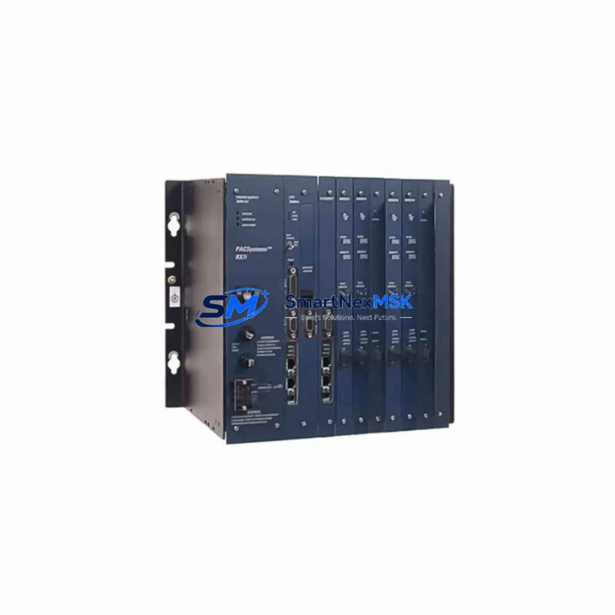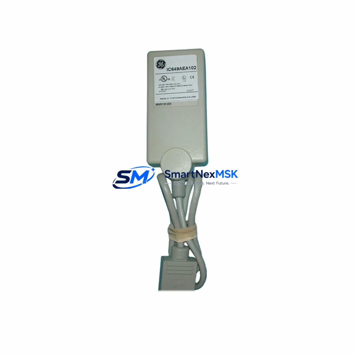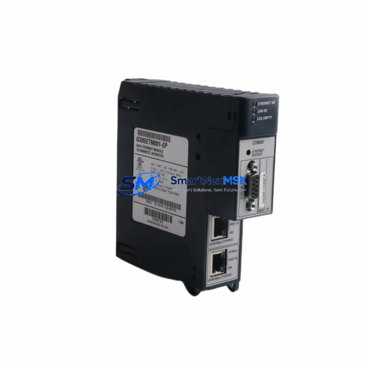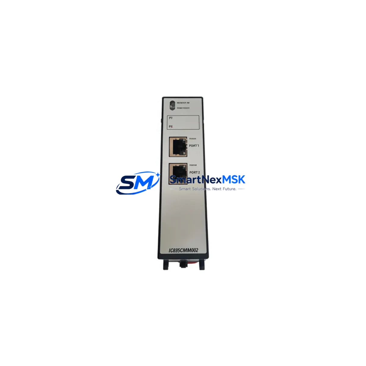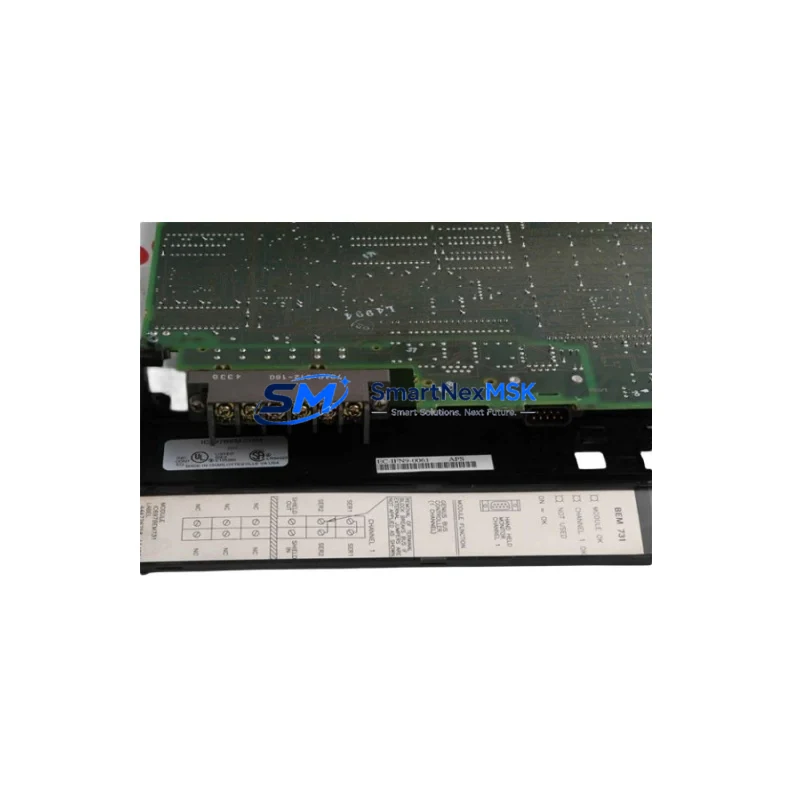
GE IC750-P5-G5-S5-HI-A1-R-E Retrofit-Ready Communication Module: Compatible Upgrade for VersaMax Control Systems
The GE IC750-P5-G5-S5-HI-A1-R-E is a retrofit-ready communication module engineered for seamless integration into existing GE VersaMax Series automation platforms. As legacy control systems age and original spare parts become increasingly difficult to source, this module provides a reliable, protocol-compatible replacement path that minimizes engineering rework and eliminates the need for full system redesign. Whether you are managing a planned upgrade cycle or responding to an unplanned failure on the production floor, the IC750-P5-G5-S5-HI-A1-R-E is stocked and ready to ship.
Designed for industrial environments where uptime is non-negotiable, this module supports the communication architecture native to the VersaMax platform, including compatibility with the VersaMax rack backplane and standard I/O expansion configurations. Engineers replacing discontinued GE Fanuc communication modules will find that the IC750-P5-G5-S5-HI-A1-R-E maintains the same slot footprint and terminal interface, reducing the time required for physical installation and wiring adaptation. Before installation, technicians should verify power supply capacity within the control cabinet — particularly when the existing IC200PWR002 or IC200PWR101 power supply module is already operating near its rated output — to ensure stable operation after the module swap.
Terminal wiring compatibility is a critical checkpoint during any retrofit. The IC750-P5-G5-S5-HI-A1-R-E uses the same connector pinout convention as its predecessor modules in the VersaMax family, which simplifies field wiring without requiring new terminal block assemblies. However, technicians should cross-reference the existing wiring diagram against the module’s I/O channel mapping to confirm signal assignments, especially in applications where the original IC200MDL640 or IC200MDL730 discrete I/O modules share the same communication segment.
Backplane interface compatibility is confirmed for standard VersaMax rack assemblies, including the IC200CHS002 and IC200CHS022 carrier configurations. Module addressing should be verified in the programming environment — typically Proficy Machine Edition — prior to going live. If the replacement module occupies the same rack slot as the original, the hardware configuration in the PLC program may require only a minor update to reflect the new module reference, preserving the existing ladder logic and function block structure without requiring a full program rewrite.
For systems that include HMI integration via CIMPLICITY or iFIX, screen tag bindings tied to the communication module’s data registers should be validated after the swap. In most VersaMax retrofit scenarios, tag addresses remain consistent, but any changes to the module’s I/O reference table should be reflected in the HMI project before operator handover. Communication links to upstream SCADA systems or DCS platforms — including those using Ethernet Global Data (EGD) or SRTP protocols — should be tested end-to-end as part of the commissioning checklist.
All units are subject to pre-shipment functional testing, covering power-on initialization, communication handshake verification, and I/O channel integrity checks. Each IC750-P5-G5-S5-HI-A1-R-E module ships with a 12-month warranty covering manufacturing defects and functional failures under normal operating conditions. Inventory is maintained in-stock to support urgent replacement orders with fast dispatch.
Upgrade Compatibility Table
| Parameter | Details |
|---|---|
| Compatible Platform | GE VersaMax Series PLC |
| Backplane Interface | VersaMax rack backplane (IC200CHS002, IC200CHS022) |
| Communication Protocol | SRTP, EGD, Ethernet (platform-dependent) |
| Installation Requirement | Same slot footprint as original VersaMax communication modules |
| Replacement Compatibility | Drop-in replacement for discontinued GE Fanuc VersaMax comm modules |
| Programming Environment | Proficy Machine Edition (GE) |
| Commissioning Notes | Verify module address, I/O reference table, and HMI tag bindings |
| Warranty | 12 months from date of shipment |
Retrofit Planning for Existing Automation Systems
A successful retrofit begins well before the module arrives on-site. Start by auditing the existing control cabinet layout to confirm rack slot availability and verify that the IC200PWR002 power supply module can support the additional load introduced by the replacement communication module. In multi-rack configurations using the IC200CHS022 expansion carrier, confirm that the backplane communication bus is intact and that no existing IC200MDL640 discrete input modules or IC200ALG230 analog output modules are reporting faults that could mask post-installation issues.
For systems that include a VersaMax MICRO controller or a VersaMax Network Interface Unit (NIU) as the primary CPU, the IC750-P5-G5-S5-HI-A1-R-E integrates within the same hardware family, preserving the existing network topology. If the system uses a GE IC200USB001 programming cable for local configuration, ensure the cable driver is current before connecting to the replacement module for initial setup. Remote I/O segments connected via IC200PBI001 PROFIBUS interface modules should be verified for address conflicts after the communication module is installed.
Document all existing module addresses, I/O reference assignments, and communication parameters before beginning the physical swap. This documentation serves as the baseline for post-installation verification and significantly reduces troubleshooting time if unexpected behavior occurs during commissioning.
Downtime Control During System Migration
Minimizing production downtime during a communication module replacement requires a structured approach. Begin by backing up the full PLC program — including all hardware configuration, ladder logic, function blocks, and data tables — using Proficy Machine Edition before powering down the rack. Store the backup on an isolated engineering workstation and verify the backup file integrity before proceeding.
Power down the control cabinet in the correct sequence: disable field outputs first, then shut down the CPU, and finally remove power from the rack. This sequence protects connected field devices and prevents uncontrolled output states during the module swap. The IC750-P5-G5-S5-HI-A1-R-E can typically be seated and secured within minutes, after which power can be restored in reverse order.
After power-up, confirm that the module initializes correctly by checking the status LEDs and reviewing the PLC fault table in Proficy Machine Edition. Restore communication links to SCADA or DCS systems and verify that all HMI screens are displaying live data before releasing the system to production. A structured commissioning checklist — covering power-on, communication handshake, I/O scan, HMI validation, and SCADA link confirmation — ensures that no step is missed and that the system is returned to full operation with confidence.
Retrofit Support FAQ
Q: Is the IC750-P5-G5-S5-HI-A1-R-E a direct drop-in replacement for discontinued GE VersaMax communication modules?
A: Yes. The IC750-P5-G5-S5-HI-A1-R-E is designed as a compatible replacement for discontinued modules within the GE VersaMax communication family. It maintains the same rack slot footprint and backplane interface, allowing installation without mechanical modification to the existing rack assembly.
Q: What commissioning steps are required after installation?
A: After physical installation, verify the module address in Proficy Machine Edition, confirm the I/O reference table matches the original configuration, test all communication links (SRTP/EGD as applicable), and validate HMI tag bindings before returning the system to production.
Q: Does the module require wiring changes at the terminal block level?
A: In most retrofit scenarios, no wiring changes are required. The IC750-P5-G5-S5-HI-A1-R-E uses the same connector convention as standard VersaMax communication modules. Technicians should cross-reference the existing wiring diagram to confirm signal assignments before powering up.
Q: What does the 12-month warranty cover?
A: The 12-month warranty covers manufacturing defects and functional failures under normal operating conditions from the date of shipment. All units undergo pre-shipment functional testing including power-on initialization, communication handshake verification, and I/O channel integrity checks prior to dispatch.
© 2026 SMARTNEXMSK. All rights reserved.
Original Source: https://smartnexmsk.com
Contact: [email protected] | +86 18259474341