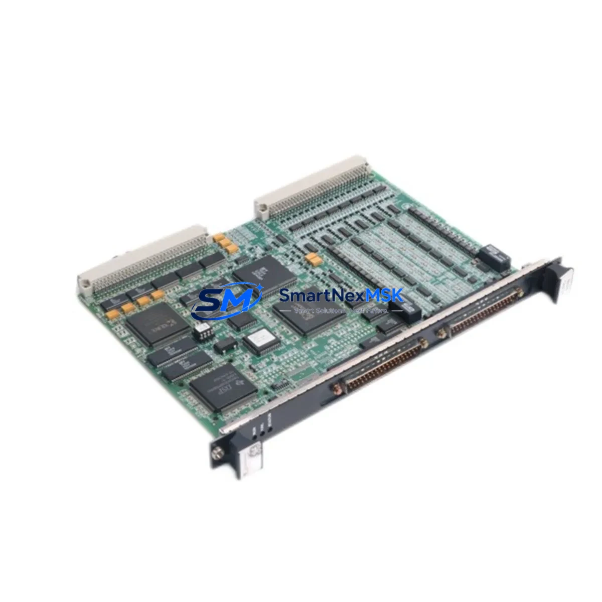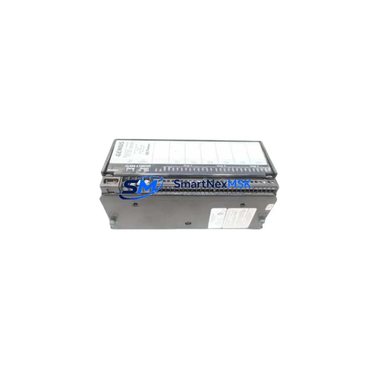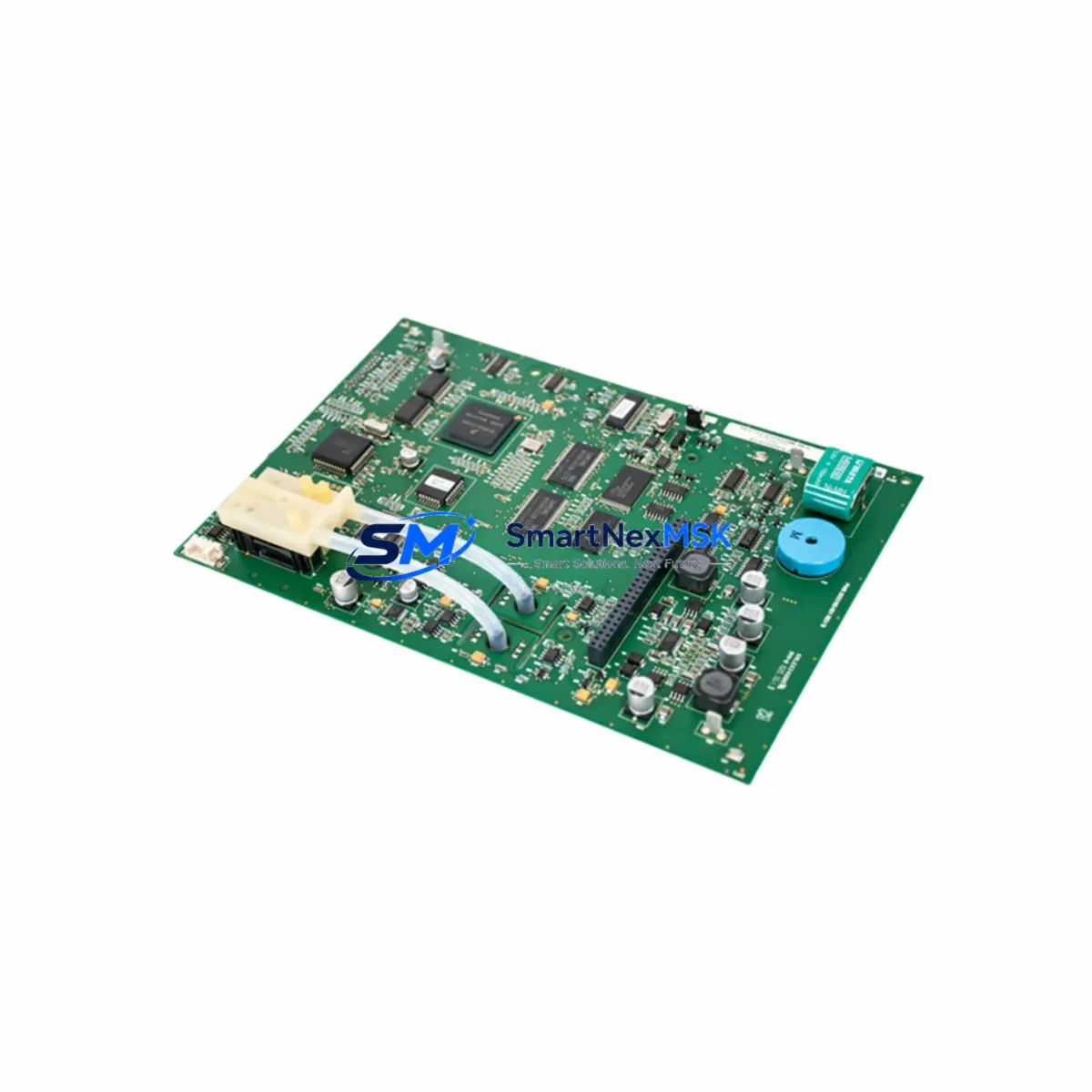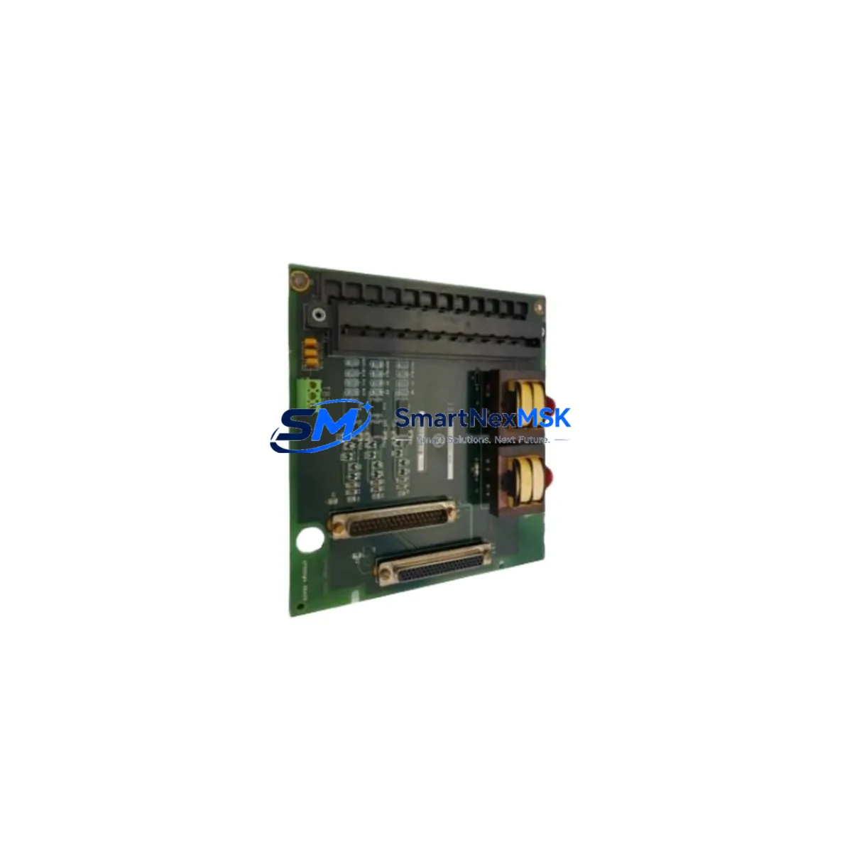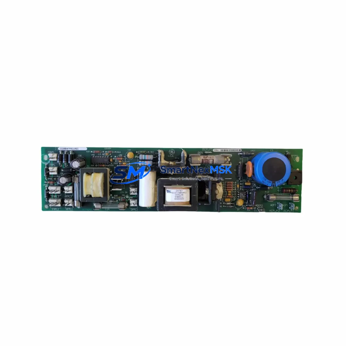
GE IS200HFPAG1AEC Retrofit-Ready Power Supply for Mark VI Control Systems
The GE IS200HFPAG1AEC is a high-frequency power supply board engineered for the GE Mark VI Turbine Control System, one of the most widely deployed distributed control platforms in power generation, oil & gas, and heavy industrial environments. As legacy Mark VI installations approach end-of-life support cycles, the IS200HFPAG1AEC has become a critical retrofit component for engineers tasked with extending system uptime, replacing failed boards, and modernizing aging control cabinets without full platform migration.
Whether you are replacing a failed unit on an emergency basis or executing a planned control system upgrade, the IS200HFPAG1AEC delivers the electrical performance and form-factor compatibility required for seamless integration into existing Mark VI racks and enclosures. This board is a direct functional replacement for obsolete or discontinued GE power supply modules within the Mark VI architecture, and it is fully compatible with the UCSC, UCSC1, and UCSC2 controller cards commonly found in Mark VI simplex and TMR (Triple Modular Redundant) configurations.
Upgrade Compatibility Table
| Parameter | Details |
|---|---|
| Compatible Platform | GE Mark VI Turbine Control System |
| Compatible Controllers | UCSC, UCSC1, UCSC2 |
| Form Factor | Standard Mark VI VME-style backplane slot |
| Input Voltage | 120/240 VAC, 50/60 Hz (auto-ranging) |
| Output Rails | +5 VDC, ±15 VDC, +24 VDC (board-level distribution) |
| Backplane Interface | Mark VI standard backplane connector — no adapter required |
| Communication Compatibility | Compatible with IONet (Ethernet-based I/O network) and ARCNET legacy links |
| Replaces Discontinued Models | IS200HFPAG1A, IS200HFPAG1B (earlier revisions) |
| Installation Requirement | No hardware modification; slot-in replacement |
| Commissioning Note | Verify module address assignment via ToolboxST after installation |
| Retrofit Recommendation | Inspect terminal block wiring and backplane pins before insertion |
| Warranty | 12-Month Warranty — covers manufacturing defects and functional failure |
Retrofit Planning for Existing Automation Systems
Successful integration of the IS200HFPAG1AEC into an existing Mark VI control cabinet requires a structured pre-installation assessment. Before removing the failed or aging power supply board, engineers should document the current power budget of the rack — accounting for all installed I/O modules, communication cards, and processor boards drawing from the shared backplane. The Mark VI system typically distributes power across multiple slots, and an undersized or mismatched replacement can cause cascading faults across connected modules.
Terminal block wiring should be inspected and photographed prior to any board removal. In many retrofit scenarios involving older Mark VI cabinets, the IS200TBCIH1C terminal board and associated IS200TBCIH1B interface boards remain in service and must be verified for connector integrity. Corroded or loose terminal connections are a common root cause of power instability that is often misdiagnosed as a board failure.
For systems running IONet communications, confirm that the Ethernet switch infrastructure — often a GE IS420ESWAH1A or equivalent managed switch — is functioning correctly before attributing power anomalies to the supply board. In TMR configurations, the IS200TSVOH1A voter module and associated IS200VTURH1BDB turbine control I/O boards must remain synchronized during the replacement window to avoid spurious trips.
If the control system includes legacy ARCNET communication links alongside newer IONet segments, verify that the IS200ACLAH1A ARCNET communication board is not affected by the power interruption. ARCNET nodes can lose their address tables during power cycling and may require re-initialization via ToolboxST configuration software after the IS200HFPAG1AEC is installed and powered up.
For sites where the Mark VI interfaces with a GE Cimplicity HMI or third-party SCADA system, coordinate the replacement window with the control room operator to suppress alarms and prevent false process trips. HMI screen updates and historian tags tied to the power supply status point should be temporarily inhibited during the swap. After restoration, verify that all IS200IOCIH1B I/O controller interface boards are reporting correctly in the ToolboxST diagnostic view before returning the unit to automatic control.
Where the retrofit involves upgrading from an earlier Mark V platform to Mark VI, additional planning is required for I/O mapping, program logic migration, and HMI screen redevelopment. The IS200HFPAG1AEC is not backward-compatible with Mark V racks, but it is a key building block in a phased Mark VI deployment that reuses existing field wiring and junction boxes.
Downtime Control During System Migration
Minimizing unplanned downtime is the primary operational concern when replacing a power supply board in a live turbine or process control environment. The IS200HFPAG1AEC replacement procedure should be executed during a scheduled maintenance window, with a pre-staged spare board that has been bench-tested and verified against the original unit’s output specifications.
Before initiating the swap, export the current ToolboxST project file and store it on an isolated engineering workstation. This preserves the complete I/O configuration, module addressing, alarm setpoints, and control logic in the event that a firmware or configuration discrepancy is discovered after installation. Do not rely solely on the controller’s onboard memory for configuration backup.
In simplex Mark VI configurations, the power supply replacement will require a controlled shutdown of the affected controller. Coordinate with the operations team to place the turbine or process unit in a safe hold state before de-energizing the rack. In TMR configurations, it may be possible to replace the power supply in one leg while the remaining two legs maintain control — consult the site-specific TMR maintenance procedure before attempting a hot-swap.
After installation, power up the rack in stages and monitor the ToolboxST diagnostic panel for fault codes. Confirm that all I/O modules — including any IS200VSVOH1B servo control boards or IS200TREGH1A turbine regulation boards — are communicating correctly before releasing the unit to automatic control. A full functional test of the protection logic, including overspeed and flame detection channels, should be completed before returning to service.
All replacement boards supplied by SMARTNEXMSK are shipped with a 12-month warranty covering manufacturing defects and functional failure under normal operating conditions. Each unit undergoes pre-shipment functional testing to verify output voltage stability, backplane connector integrity, and thermal performance. Expedited shipping options are available for emergency breakdown situations, with same-day dispatch for in-stock units.
Retrofit Support FAQ
Q1: Is the IS200HFPAG1AEC a direct drop-in replacement for earlier IS200HFPAG1A and IS200HFPAG1B revisions?
Yes. The IS200HFPAG1AEC is the current production revision of the IS200HFPAG1A family and is fully backward-compatible with earlier revisions in terms of backplane connector pinout, output voltage rails, and physical form factor. No hardware modification or adapter is required for installation in existing Mark VI racks.
Q2: What commissioning steps are required after installing the IS200HFPAG1AEC?
After physical installation, power up the rack and open ToolboxST to verify that the module is recognized at the correct slot address. Check all output voltage rails using a calibrated multimeter at the backplane test points. Confirm that downstream I/O modules and communication cards are reporting no faults. If ARCNET links are present, verify node address assignments and re-initialize if necessary. Complete a full I/O loop check before returning to automatic control.
Q3: How do I verify wiring compatibility before installation?
Review the Mark VI system wiring diagrams for the affected rack and confirm that the terminal block assignments on the associated interface board match the IS200HFPAG1AEC input requirements. Inspect all terminal screws for tightness and check for signs of insulation degradation or corrosion. Verify that the incoming AC supply voltage is within the board’s auto-ranging input specification (120/240 VAC) before energizing.
Q4: What does the 12-month warranty cover, and what is the return process?
The 12-month warranty covers manufacturing defects and functional failure under normal operating conditions. It does not cover damage resulting from incorrect installation, overvoltage events, or physical mishandling. To initiate a warranty claim, contact SMARTNEXMSK with the original order number, a description of the fault, and photographic evidence of the installation. Replacement or repair will be arranged within 5 business days of claim approval.
© 2026 SMARTNEXMSK. All rights reserved.
Original Source: https://smartnexmsk.com
Contact: [email protected] | +86 18259474341