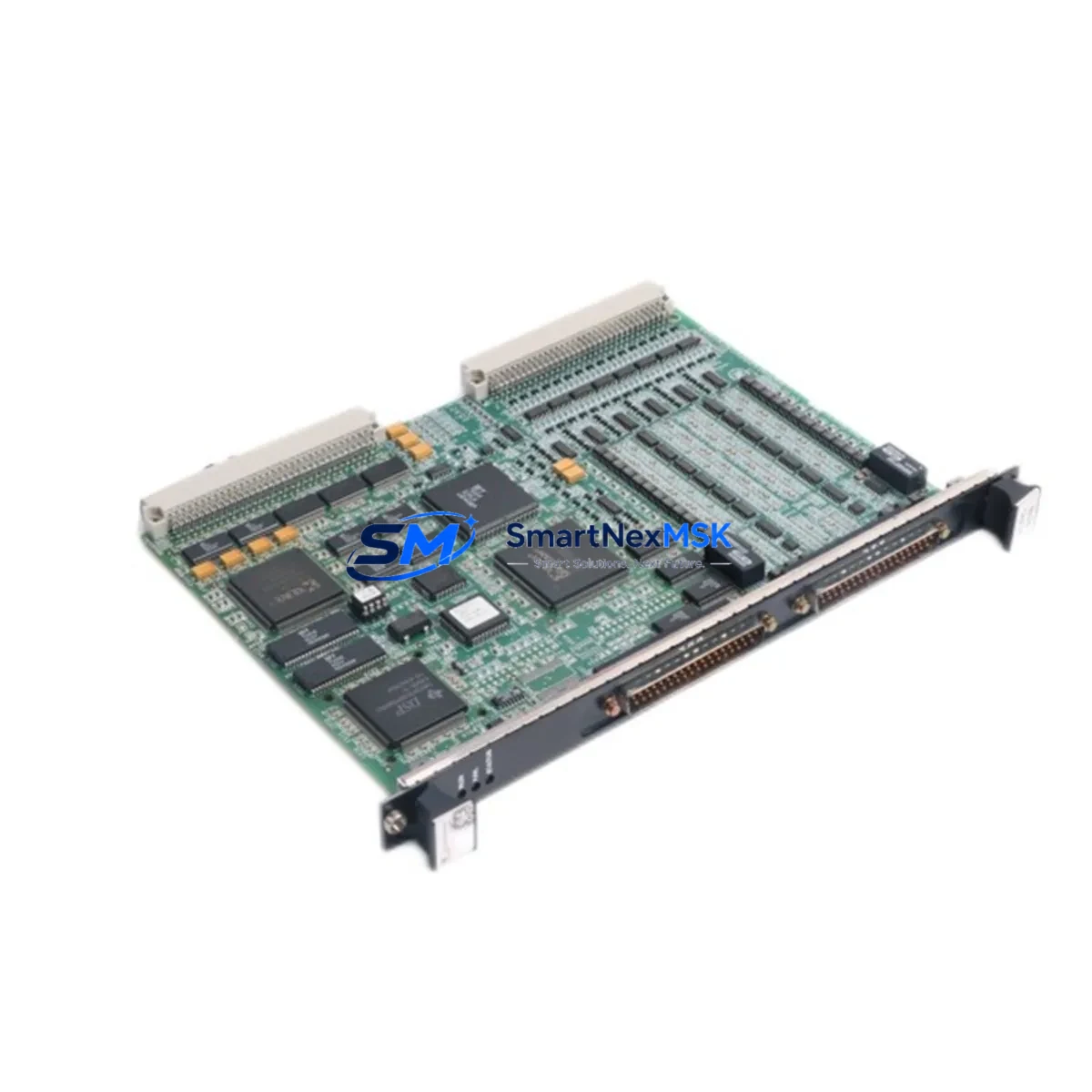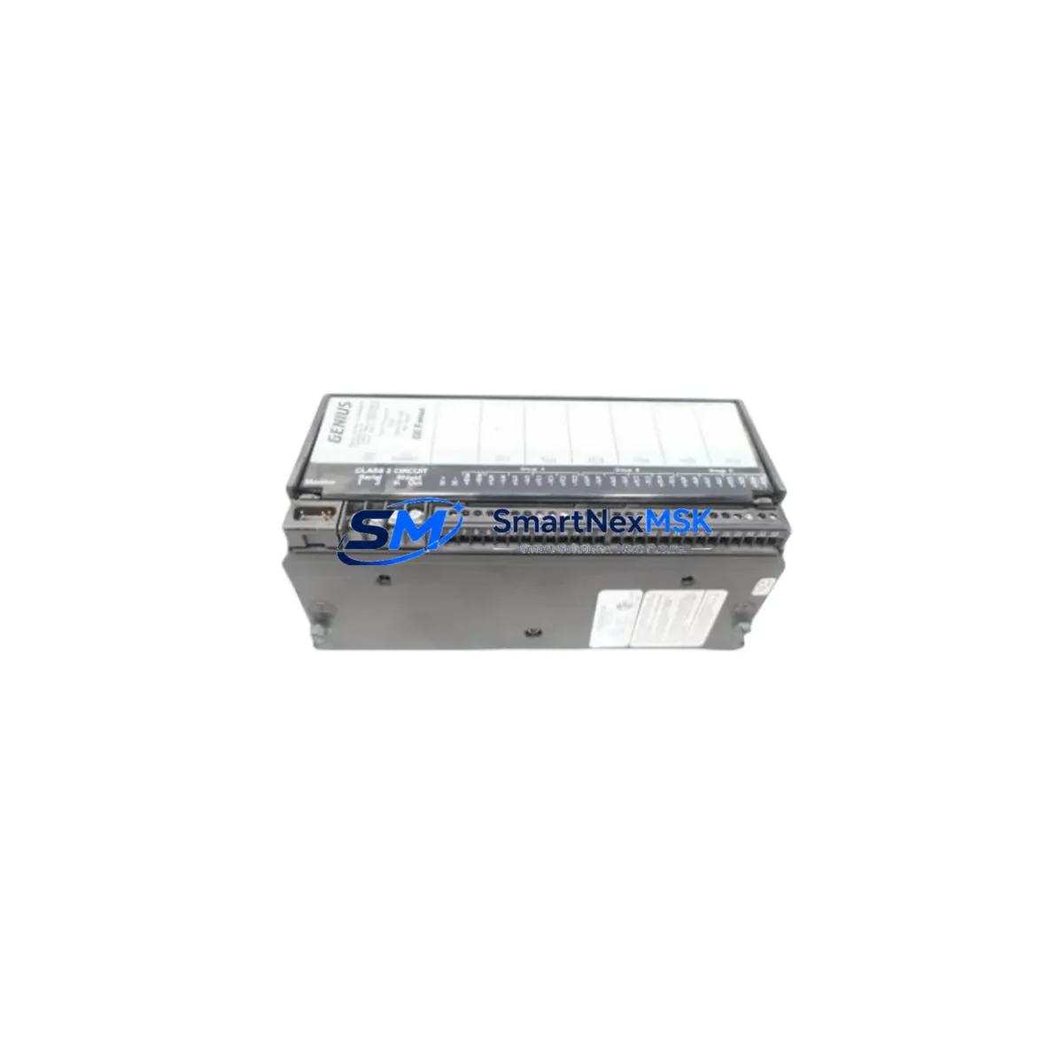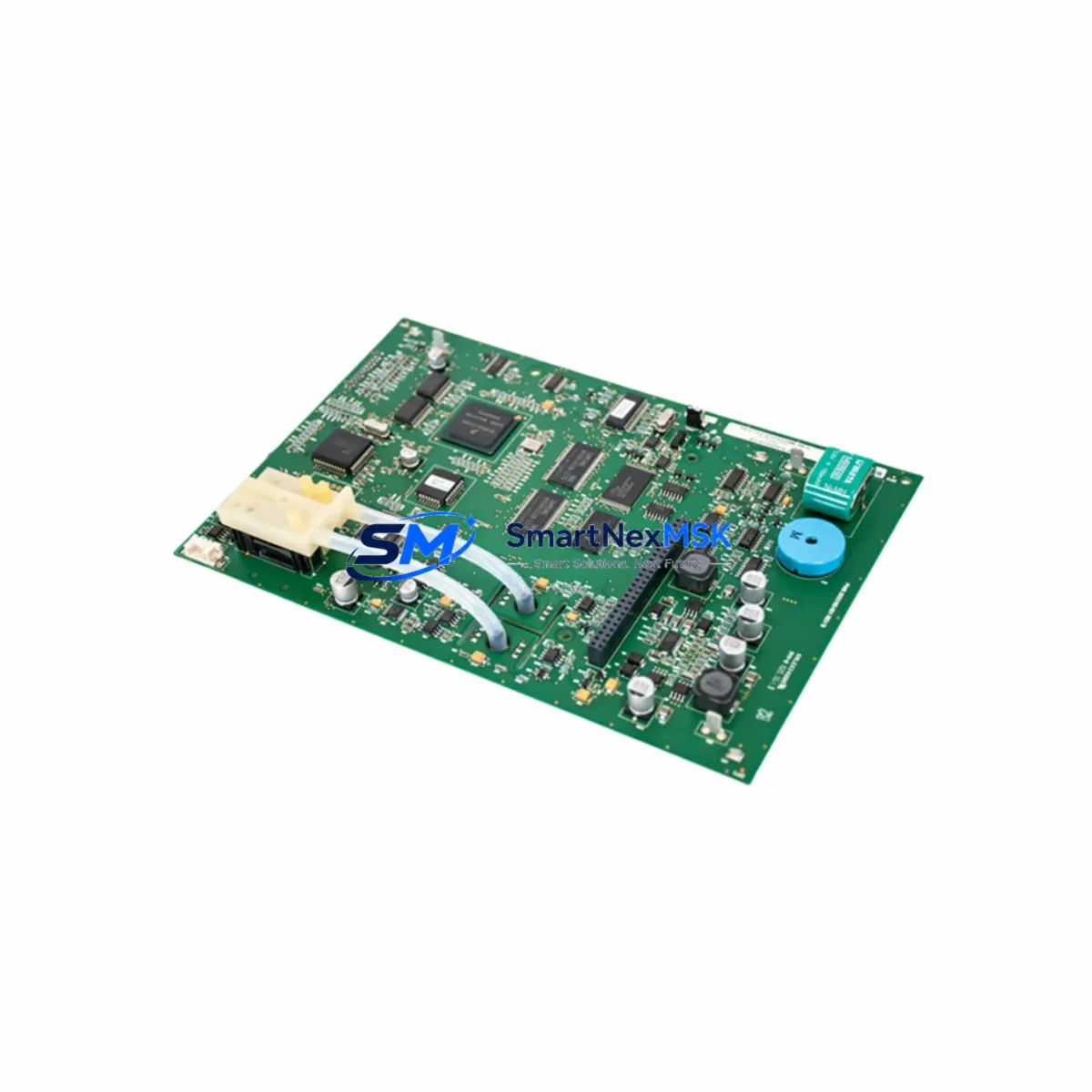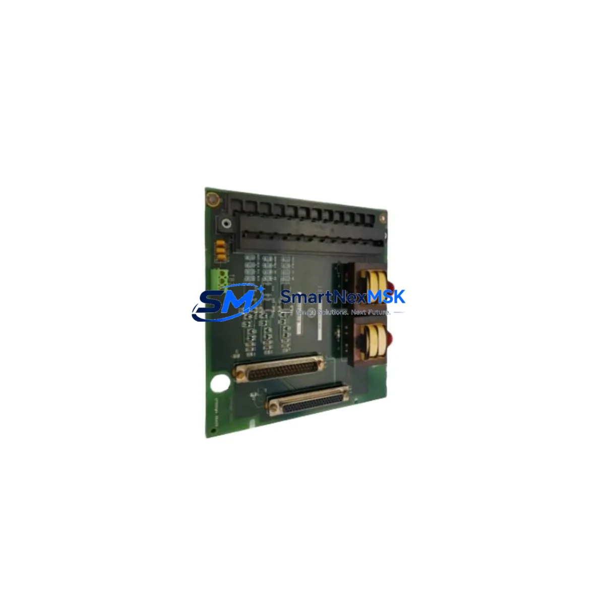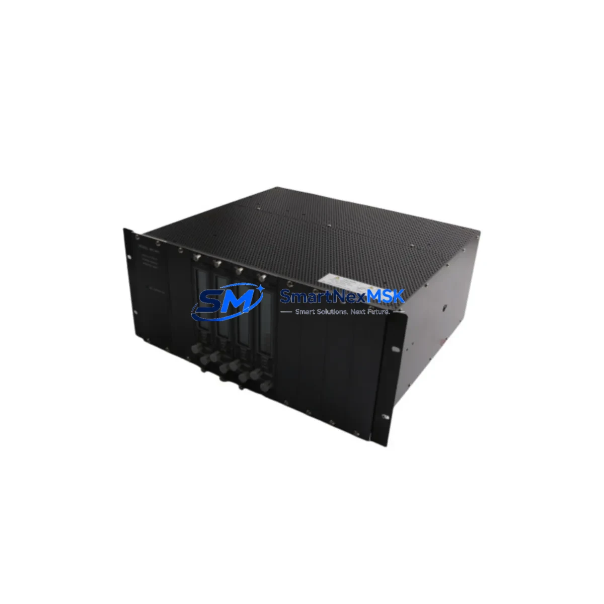
GE VM-5H3 VM-5Z VM-5K Maintenance-Ready Spare VM-5 Series Automation
For maintenance engineers managing GE VM-5 Series control systems, unplanned downtime caused by a failed power supply monitor rack is one of the most disruptive events on the plant floor. The GE VM-5H3, VM-5Z, and VM-5K are original, factory-specification power supply monitor rack modules designed for the VM-5 Series automation platform — a proven architecture widely deployed in process control, discrete manufacturing, and utility infrastructure. Sourcing a verified, compatible replacement spare is the fastest path to restoring system integrity and resuming production.
Each unit supplied by SMARTNEXMSK is an original GE component, not a third-party substitute. Before dispatch, every module undergoes functional verification including power rail output testing, rack interface continuity checks, and visual inspection for connector integrity. A 12-month warranty is included with every shipment, covering manufacturing defects and functional failures under normal operating conditions. Units are packaged in anti-static, shock-resistant materials suitable for international freight.
Spare Maintenance Table
| Parameter | Specification / Value |
|---|---|
| Part Numbers | VM-5H3 / VM-5Z / VM-5K |
| Brand / Manufacturer | GE (General Electric Automation) |
| Series | VM-5 Series |
| Product Type | Power Supply Monitor Rack |
| Country of Origin | Germany |
| Compatibility | GE VM-5 Series PLC / Control System Racks |
| Application Environment | Industrial process control, discrete manufacturing, utility automation |
| Installation | Direct rack-mount replacement; observe OEM torque and grounding specifications |
| Condition | Original spare — new or tested-serviceable as specified at order |
| Pre-shipment Testing | Power rail output, rack interface continuity, connector integrity |
| Warranty | 12 Months — covers manufacturing defects and functional failures |
| Packaging | Anti-static, shock-resistant; suitable for international freight |
| Lead Time | Typically 3–7 business days; expedited options available |
| Long-term Supply | Stocked for legacy system support; multi-unit orders accepted |
Maintenance Planning for Continuous Operation
When a VM-5H3, VM-5Z, or VM-5K power supply monitor rack is flagged during routine inspection or fails in service, experienced maintenance engineers know that the replacement workflow extends well beyond swapping the module itself. A thorough site assessment prevents repeat failures and ensures the restored system meets its original design specification.
Begin with the upstream power feed. Verify that the AC input voltage and frequency supplied to the rack enclosure are within the tolerances specified in the GE VM-5 Series system manual. A degraded or noisy power feed is a common root cause of premature power supply module failure. If the facility uses a dedicated UPS or power conditioner for the control cabinet, inspect its output waveform and battery health before commissioning the replacement rack.
Within the same control cabinet, inspect the VM-5 Series backplane for signs of oxidation, bent connector pins, or heat discoloration at the rack slot where the failed module was seated. A damaged backplane connector will cause the replacement module to fail prematurely. If the backplane shows wear, a GE VM-5 backplane assembly should be added to the maintenance order alongside the power supply monitor rack.
Check all DC bus fuses and circuit breakers in the power distribution section of the cabinet. A blown fuse downstream of the power supply rack is often a symptom of a short circuit or overload condition that caused the original module failure — replacing the rack without clearing the fault will damage the new unit. Similarly, inspect terminal blocks and wiring harnesses connected to the rack’s output rails for insulation breakdown, loose terminations, or corrosion, particularly in high-humidity or chemically aggressive environments.
For systems that include GE VM-5 Series I/O modules — analog input, digital output, or thermocouple cards — verify that each module’s power draw is within the rack’s rated capacity after the replacement. An overloaded rack is a leading cause of thermal stress and early failure. If the system has expanded since original commissioning, a power budget recalculation is recommended.
Communication integrity should also be validated. If the VM-5 rack interfaces with a GE Series 90 PLC CPU or a GE Profibus / Genius Bus communication module, confirm that the network addresses and baud rate settings are correctly restored after the rack replacement. Communication faults that appear after a hardware swap are frequently caused by incorrect DIP switch or parameter settings on the replacement module rather than a hardware defect.
For facilities running legacy GE Mark V or Mark VI turbine control systems alongside VM-5 Series racks, it is advisable to maintain a coordinated spare parts inventory that includes signal isolators for 4–20 mA loops, relay output modules, and HMI interface cards. These components share the same maintenance cycle and are subject to the same environmental stressors as the power supply monitor rack. Procuring them as a coordinated spare set reduces emergency sourcing lead times and simplifies cabinet-level maintenance scheduling.
Finally, document the replacement event in the plant’s CMMS (Computerized Maintenance Management System), recording the failed module’s serial number, failure mode, operating hours, and the environmental conditions at the time of failure. This data supports predictive maintenance scheduling and helps justify proactive spare stock levels to procurement management.
Site Replacement Workflow
Step 1 — Isolation and Lockout/Tagout: De-energize the control cabinet following site LOTO procedures. Confirm zero energy state on all power rails before opening the rack enclosure.
Step 2 — Module Removal: Document the existing wiring and connector positions with photographs before disconnecting. Label all cables if not already marked. Remove the failed VM-5H3, VM-5Z, or VM-5K module by releasing the rack retention mechanism and sliding the module clear of the backplane connector.
Step 3 — Backplane and Slot Inspection: Inspect the vacated rack slot for debris, oxidation, or physical damage. Clean the backplane connector with approved contact cleaner if contamination is present. Do not proceed with installation if the backplane connector is damaged — replace the backplane first.
Step 4 — Replacement Module Verification: Confirm the replacement module’s part number (VM-5H3, VM-5Z, or VM-5K as applicable) matches the system’s bill of materials. Verify firmware revision compatibility if the system has been updated since original installation. Check that all DIP switches or jumper settings on the replacement module match the configuration of the removed unit.
Step 5 — Installation and Re-energization: Seat the replacement module firmly into the rack slot, ensuring full backplane connector engagement. Reconnect all wiring per the documented positions. Re-energize the cabinet in stages — apply control power first, verify power supply outputs before enabling field power to I/O modules.
Step 6 — Functional Verification: Confirm that the PLC CPU recognizes the replacement rack, all I/O modules report healthy status, and communication links are re-established. Run a short functional test cycle before returning the system to automatic operation. Log the replacement in the CMMS and update the spare parts inventory record.
Spare Parts Support FAQ
Q1: Are the VM-5H3, VM-5Z, and VM-5K interchangeable, or are they distinct part numbers for different configurations?
These are distinct GE part numbers within the VM-5 Series, each corresponding to a specific rack configuration or power supply rating. Always verify the exact part number against your system’s bill of materials or the label on the failed module before ordering. SMARTNEXMSK can assist with cross-reference verification if you provide your system’s configuration documentation.
Q2: How do I verify compatibility before installation if my system has been modified since original commissioning?
Request the GE VM-5 Series system manual for your specific rack configuration and compare the replacement module’s rated specifications against the current system load. If the system has been expanded with additional I/O modules, recalculate the total power draw to confirm the replacement rack’s output capacity is sufficient. SMARTNEXMSK provides pre-shipment functional testing documentation that can be used as a baseline for compatibility verification.
Q3: What does the 12-month warranty cover, and what is the claims process?
The 12-month warranty covers manufacturing defects and functional failures under normal operating conditions as defined by GE’s original product specification. It does not cover damage caused by incorrect installation, overvoltage events, or operation outside rated environmental parameters. To initiate a warranty claim, contact SMARTNEXMSK with the order number, a description of the failure mode, and photographic evidence of the installation. Replacement or repair will be arranged within the warranty period.
Q4: Can SMARTNEXMSK support long-term supply for legacy VM-5 Series systems that are no longer in GE’s active production catalog?
Yes. SMARTNEXMSK specializes in long-term spare parts support for legacy industrial automation systems, including discontinued GE product lines. We maintain stock of VM-5 Series components and can source additional units through verified supply channels. Multi-unit blanket orders are accepted to support planned maintenance programs and spare parts inventory strategies for extended system lifecycles.
© 2026 SMARTNEXMSK. All rights reserved.
Original Source: https://smartnexmsk.com
Contact: [email protected] | +86 18259474341