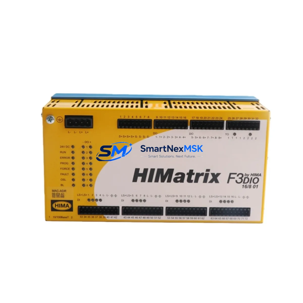
HIMA F3-DIO-16/8-01 Retrofit-Ready Safety I/O for HIMax Control Systems
The HIMA F3-DIO-16/8-01 is a SIL 3-certified digital safety I/O module designed for seamless integration into HIMax safety PLC platforms. With 16 digital inputs and 8 digital outputs, this module is engineered to serve as a direct retrofit replacement for aging or discontinued safety I/O components within existing HIMax control cabinets. Whether you are upgrading a legacy safety architecture, recovering from an unplanned module failure, or executing a planned system modernization, the F3-DIO-16/8-01 delivers the reliability, protocol compatibility, and field-proven performance that industrial safety engineers demand.
Sourced from verified supply channels and subject to full functional testing prior to shipment, each unit is backed by a 12-month warranty covering both hardware integrity and operational conformance. Global logistics support ensures fast delivery to process plants, offshore platforms, power generation facilities, and chemical processing sites where HIMax safety systems are widely deployed.
Upgrade Compatibility Table
| Parameter | F3-DIO-16/8-01 Specification | Retrofit Notes |
|---|---|---|
| Digital Inputs | 16 × 24 VDC, SIL 3 | Direct pin-compatible with prior HIMax DI modules |
| Digital Outputs | 8 × 24 VDC, SIL 3 | Verify load current per output channel before wiring |
| Safety Integrity Level | SIL 3 (IEC 61508) | Maintain SIL 3 loop integrity; re-validate SIL calculation after swap |
| Communication Protocol | ProfiSafe over PROFIBUS / PROFINET | Confirm F-Address assignment matches original module configuration |
| Backplane Interface | HIMax standard backplane connector | Compatible with HIMax CPU racks; no mechanical adapter required |
| Module Address | Configurable via SILworX engineering tool | Re-import module address from existing project backup before go-live |
| Power Supply Requirement | 24 VDC (supplied via backplane) | Verify HIMax power supply module (e.g., F3 PE 14/8 01) capacity margin |
| Installation Format | Plug-in module, HIMax rack-mount | Hot-swap capable in redundant configurations; confirm with site SOP |
| Engineering Software | SILworX (HIMA) | Use existing project file; update hardware configuration tree after swap |
| Warranty | 12 Months | Covers hardware defects and functional non-conformance from shipment date |
Retrofit Planning for Existing Automation Systems
Successful integration of the F3-DIO-16/8-01 into an existing HIMax safety system begins with a thorough pre-retrofit audit. Engineers should start by reviewing the current HIMax CPU module configuration — typically a unit such as the HIMax X-CPU 01 or HIMax X-CPU 04 — to confirm that the backplane slot assignment and module addressing scheme are documented and backed up in the SILworX project archive. Any discrepancy between the physical rack layout and the software hardware tree must be resolved before the replacement module is installed.
Terminal wiring is a critical checkpoint. The F3-DIO-16/8-01 uses a standard HIMax field wiring connector, and technicians should verify that existing cable labels, terminal block assignments, and wire gauges conform to the module’s input/output specifications. In installations where the original wiring was routed through a HIMA F3 XT 16/8 01 terminal expansion unit or a marshalling panel, the field wiring can typically be transferred without modification, significantly reducing retrofit labor time.
For sites running ProfiSafe communication over PROFIBUS DP, the F-Address (ProfiSafe address) of the replacement module must match the address stored in the safety PLC project. If the original module’s F-Address was set via hardware DIP switches, the new unit must be configured identically before insertion. Sites that have migrated to PROFINET-based ProfiSafe should confirm that the GSD or GSDML device description file version is compatible with the installed HIMax firmware revision.
Power budget verification is mandatory when adding or replacing I/O modules in an existing HIMax rack. The installed HIMax power supply module — such as the F3 PE 14/8 01 or a redundant pair — must have sufficient current headroom to support the F3-DIO-16/8-01 alongside other co-installed modules, including communication modules like the F3 COM 14/8 01 and any additional analog I/O modules such as the F3-AIO-8/4-01. A rack-level power audit should be completed and documented as part of the retrofit change record.
HMI screen validation is often overlooked during module replacements. If the plant’s DCS or SCADA system — whether running on a Siemens WinCC, Wonderware InTouch, or a dedicated HIMA HIVision operator station — displays I/O channel status from the HIMax safety controller, engineers should confirm that tag mappings and alarm setpoints remain intact after the module swap. Any changes to the module’s slot position or channel numbering will require corresponding updates in the HMI project.
Finally, communication link continuity must be verified end-to-end. In systems where the HIMax controller interfaces with a Siemens S7-400 or S7-300 standard PLC via a gateway or shared PROFIBUS segment, the safety communication path should be tested under simulated process conditions before returning the system to live operation. This is particularly important in dual-channel or voted safety loops where the F3-DIO-16/8-01 participates in a 1oo2 or 2oo3 voting architecture.
Downtime Control During System Migration
Minimizing unplanned downtime is the primary operational concern when replacing safety I/O modules in a live production environment. The F3-DIO-16/8-01 supports hot-swap replacement in HIMax systems configured with redundant I/O, allowing the module to be exchanged while the redundant channel maintains process control continuity. Before initiating any hot-swap procedure, the site safety officer and control system engineer must confirm that the redundant channel is fully operational and that the safety function remains in a safe state throughout the exchange.
For non-redundant installations, a controlled shutdown window should be planned. The recommended sequence is to place the affected safety loop in bypass mode using the HIMax bypass management function within SILworX, physically replace the F3-DIO-16/8-01, restore the module configuration from the archived project file, perform a channel-by-channel I/O force test to verify wiring integrity, and then release the bypass to return the loop to automatic safety mode. This sequence typically requires between 45 minutes and 2 hours depending on the number of I/O channels involved and the complexity of the field wiring.
Program logic preservation is non-negotiable. The existing SILworX project file — including all function block logic, cause-and-effect matrices, and safety function definitions — must not be modified during the hardware replacement. Only the hardware configuration tree within the project should be updated to reflect the new module’s serial number and firmware version. A full project download is generally not required if only the hardware configuration has changed; a partial download targeting the affected module slot is sufficient and reduces the risk of inadvertently altering validated safety logic.
Post-replacement commissioning should include a witnessed functional test of each I/O channel, a review of the HIMax diagnostic log for any fault codes generated during the module initialization sequence, and a sign-off by the responsible safety engineer. All activities should be recorded in the plant’s management of change (MOC) system to maintain the safety case documentation trail required by IEC 61511 and site-specific functional safety management procedures.
Retrofit Support FAQ
Q1: Is the F3-DIO-16/8-01 a direct drop-in replacement for older HIMA HIMax digital I/O modules?
In most cases, yes. The F3-DIO-16/8-01 uses the standard HIMax backplane connector and is compatible with existing HIMax rack infrastructure. However, engineers should verify the firmware version of the installed HIMax CPU and confirm that the SILworX project hardware library supports the specific revision of the replacement module. Minor configuration updates in SILworX may be required if the firmware baseline differs from the original installation.
Q2: What wiring changes are needed when installing the F3-DIO-16/8-01?
In most retrofit scenarios, no field wiring changes are required. The module uses the same HIMax field connector pinout as its predecessors. Technicians should inspect existing cable terminations for wear or corrosion, re-torque terminal screws to the specified value, and verify that cable shielding is correctly grounded at the cabinet entry point. If the original installation used a HIMA terminal expansion unit, the field connector can be transferred directly to the new module.
Q3: How is the ProfiSafe F-Address configured on the replacement module?
The ProfiSafe F-Address is configured within the SILworX engineering environment and stored in the module’s non-volatile memory during the project download. When replacing a failed module, retrieve the F-Address from the existing SILworX project file and apply it to the new module during the commissioning download. Do not change the F-Address unless the module is being relocated to a different slot or safety function. Incorrect F-Address assignment will prevent the ProfiSafe communication from establishing and will generate a safety-relevant fault in the HIMax diagnostic system.
Q4: What does the 12-month warranty cover, and what is the process for a warranty claim?
The 12-month warranty covers hardware defects, component failures, and functional non-conformance identified under normal operating conditions from the date of shipment. Each unit undergoes pre-shipment functional testing to verify I/O channel integrity, communication interface operation, and power consumption within specification. To initiate a warranty claim, contact our technical support team with the module serial number, purchase order reference, and a description of the observed fault. Replacement units are dispatched from stock to minimize site downtime, and failed units are returned for root cause analysis.
© 2026 SMARTNEXMSK. All rights reserved.
Original Source: https://smartnexmsk.com
Contact: [email protected] | +86 18259474341