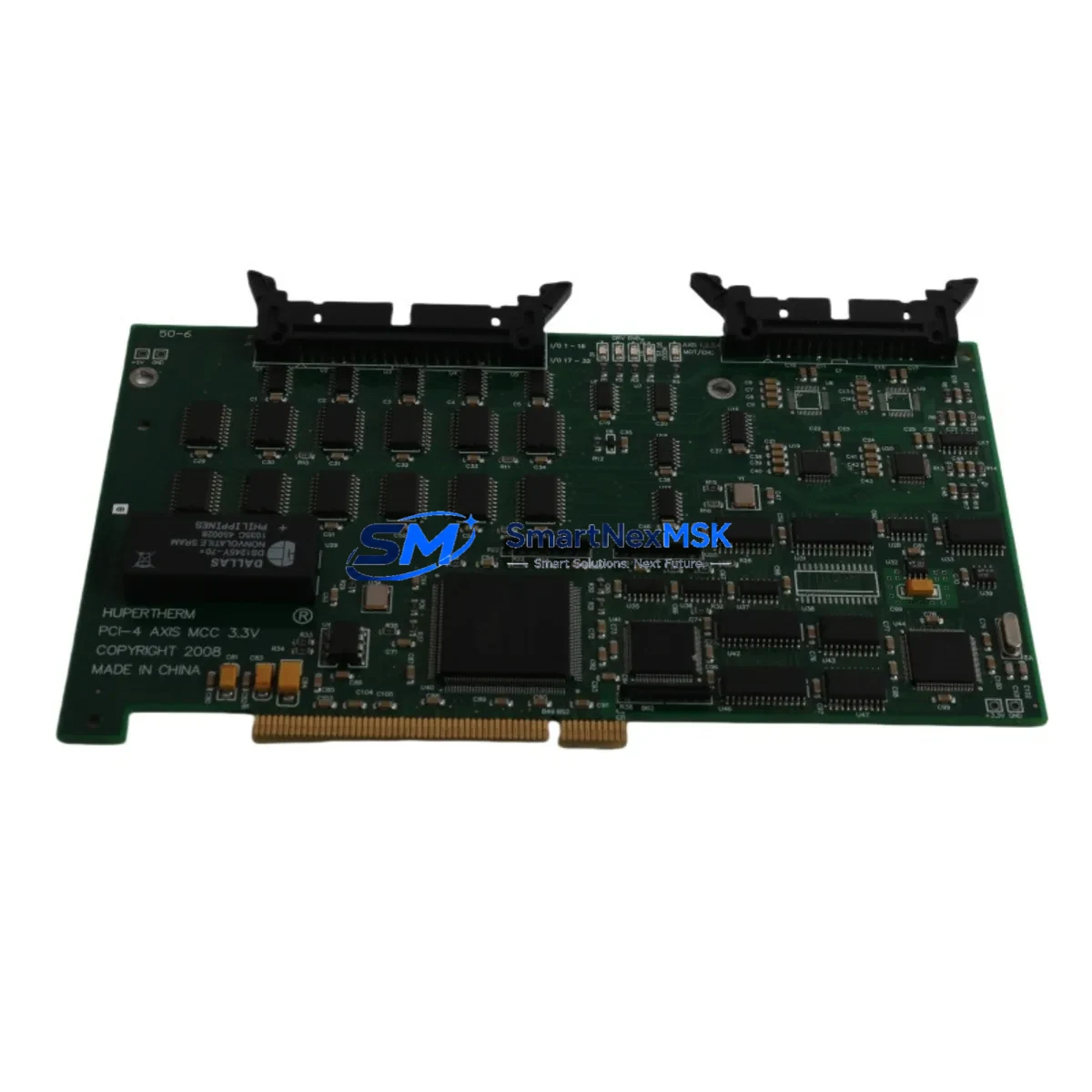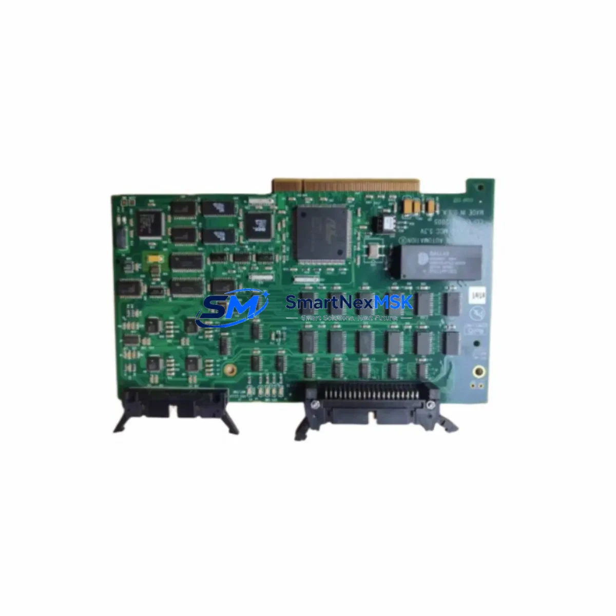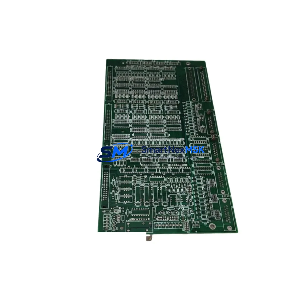
Hypertherm PCBS-0057 REV A Retrofit-Ready Servo I/O Board: Compatible Modernization for H1 Series Control Systems
The Hypertherm PCBS-0057 REV A is a servo I/O interface board engineered for drop-in compatibility with Hypertherm H1 Series CNC plasma cutting systems. As legacy H1 control platforms reach end-of-life and original spare parts become increasingly scarce, this board serves as a verified retrofit solution for system integrators, maintenance engineers, and automation specialists managing aging plasma cutting lines. Whether you are replacing a failed board in an emergency shutdown scenario or executing a planned control system upgrade, the PCBS-0057 REV A delivers the electrical and functional compatibility required to restore full servo loop integrity without requiring a full controller replacement.
Sourced from verified supply channels and subjected to pre-shipment functional testing, each unit is backed by a 12-month warranty covering manufacturing defects and functional failures under normal operating conditions. In-stock inventory is maintained to support urgent dispatch requirements, with worldwide shipping available to minimize production downtime.
Upgrade Compatibility Table
| Parameter | Details |
|---|---|
| SKU / Part Number | PCBS-0057 REV A |
| Brand | Hypertherm |
| Compatible Series | Hypertherm H1 Series CNC Plasma Control Systems |
| Board Function | Servo I/O Interface — axis feedback, drive enable, encoder signal routing |
| Replacement Scope | Direct retrofit for original PCBS-0057 REV A installations; verify REV level before installation |
| Connector / Interface | Edge connector and terminal block layout consistent with H1 backplane; confirm slot position and ribbon cable routing |
| Communication Compatibility | Parallel I/O signal architecture native to H1 control bus; no protocol conversion required |
| Installation Requirement | Power-down system before removal; discharge capacitors; re-seat encoder cables and verify axis address DIP switches |
| Commissioning Focus | Servo tuning parameters, axis homing offsets, and E-stop interlock verification post-installation |
| Warranty | 12 months from date of shipment — covers manufacturing defects and functional failures under normal use |
Retrofit Planning for Existing Automation Systems
Replacing the PCBS-0057 REV A within an operational H1 plasma system requires a structured approach that accounts for the interdependencies between the servo interface board and the broader control architecture. Before initiating the swap, engineers should document the existing axis configuration stored in the H1 main controller board, as servo gain parameters and homing offsets are typically held in non-volatile memory on the controller rather than on the interface board itself. This documentation step protects against data loss during power cycling.
The H1 system’s backplane rack must be inspected for slot integrity and connector pin condition prior to seating the replacement board. Oxidized or bent pins on the backplane edge connector are a common cause of intermittent servo faults that can be misdiagnosed as board failure. Cleaning the backplane contacts and verifying the mechanical seating of adjacent modules — including the H1 power supply module and any installed I/O expansion boards — is recommended before powering up with the new PCBS-0057 REV A.
Encoder feedback cables connecting the servo drives to the interface board should be inspected for shielding continuity and connector integrity. In many H1 installations, the servo drive units (typically analog-commanded drives matched to the H1 servo loop architecture) are connected via shielded multi-conductor cables that are routed through the control cabinet. Any damage to cable shielding can introduce noise into the encoder feedback path, causing position errors or drive faults after the board replacement — even when the new board itself is fully functional.
For systems that also include a Hypertherm HMI operator panel or a connected CNC pendant, the axis status displays and servo ready indicators should be verified after installation. HMI screen elements tied to servo status bits may require a soft reset of the display controller to refresh correctly after the interface board is replaced. Similarly, if the H1 system communicates with an upstream PLC or supervisory controller via a discrete I/O handshake — common in integrated cutting cell applications — the I/O signal mapping should be re-verified against the original wiring diagram to confirm that the replacement board’s terminal assignments match the installed field wiring.
In multi-axis H1 configurations, the axis address DIP switches on the PCBS-0057 REV A must be set to match the original board’s address configuration before installation. Incorrect axis addressing will cause the controller to fail axis initialization and may generate misleading fault codes. Reference the H1 system’s axis configuration documentation or photograph the original board’s DIP switch positions before removal.
Where the retrofit is part of a broader control system modernization — for example, migrating from the H1 platform to a newer Hypertherm controller generation or integrating a third-party motion controller — the PCBS-0057 REV A can serve as a bridge component to maintain servo loop continuity during a phased migration, allowing the cutting system to remain operational while upstream control architecture changes are implemented in stages.
Downtime Control During System Migration
Minimizing unplanned downtime during a servo interface board replacement on an H1 CNC plasma system requires preparation that begins before the system is taken offline. The most effective approach is to pre-stage the replacement PCBS-0057 REV A alongside all required tools, documentation, and consumables before initiating the shutdown sequence. This includes having the H1 system’s axis parameter printout or backup file available, the correct torque specifications for backplane mounting hardware, and a verified spare set of encoder cable connectors in case field connectors are found to be damaged during inspection.
The original program logic stored in the H1 controller is not resident on the servo interface board and will not be lost during the board swap, provided the controller’s battery-backed memory is functional. However, it is strongly recommended to perform a full program backup to an external storage device before any hardware intervention, as power cycling events during board replacement can occasionally trigger memory initialization routines on older H1 controllers.
After installing the PCBS-0057 REV A, a controlled power-up sequence should be followed: energize the control power supply first, verify that the controller completes its initialization sequence without fault codes, then enable the servo drives one axis at a time while monitoring current draw and encoder feedback signals. This staged energization approach isolates any axis-specific issues before full system operation is resumed, reducing the risk of a secondary fault extending the downtime window.
For cutting operations with strict production schedules, maintaining a spare PCBS-0057 REV A in the on-site spare parts inventory is the most reliable downtime mitigation strategy. Given the discontinued status of H1 series components, sourcing lead times from the original manufacturer are no longer predictable, making pre-positioned inventory essential for facilities that cannot tolerate extended unplanned outages.
Retrofit Support FAQ
Q: Is the PCBS-0057 REV A a direct replacement for all H1 series servo interface boards?
A: The PCBS-0057 REV A is a direct replacement for units with the same part number and revision level. H1 systems may have been produced with multiple board revisions; confirm the REV designation on the original board before ordering. If your installed board carries a different REV suffix, contact our technical team to verify cross-compatibility before installation.
Q: What commissioning steps are required after installing the replacement board?
A: After seating the board and restoring power, verify that all axis DIP switch addresses match the original configuration, confirm encoder feedback signals are present on all connected axes, perform a manual jog test on each axis at low speed before running a full cutting cycle, and verify E-stop and servo-ready interlock signals are functioning correctly. Document all commissioning steps for maintenance records.
Q: Can this board be used in a system that has been partially upgraded to a newer controller?
A: In phased migration scenarios where the H1 backplane and servo drives are retained while upstream control components are upgraded, the PCBS-0057 REV A can continue to function as the servo I/O interface provided the signal levels and connector assignments remain compatible with the new controller’s output stage. Verify signal voltage levels and I/O mapping with your system integrator before proceeding.
Q: What does the 12-month warranty cover?
A: The 12-month warranty covers manufacturing defects and functional failures under normal operating conditions from the date of shipment. It does not cover damage resulting from incorrect installation, overvoltage events, physical impact, or use outside the board’s specified operating environment. Pre-shipment functional testing is performed on all units prior to dispatch.
© 2026 SMARTNEXMSK. All rights reserved.
Original Source: https://smartnexmsk.com
Contact: [email protected] | +86 18259474341