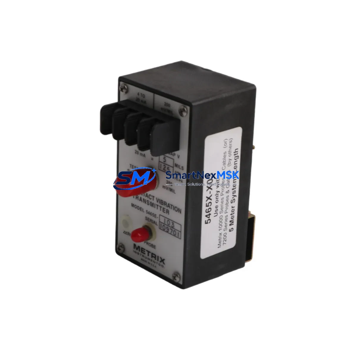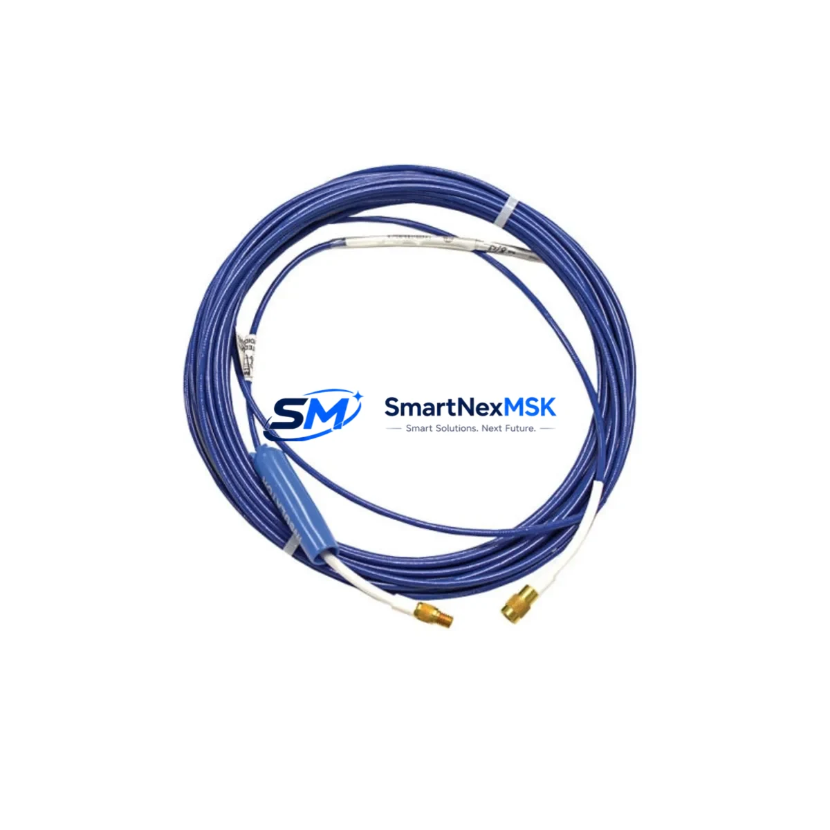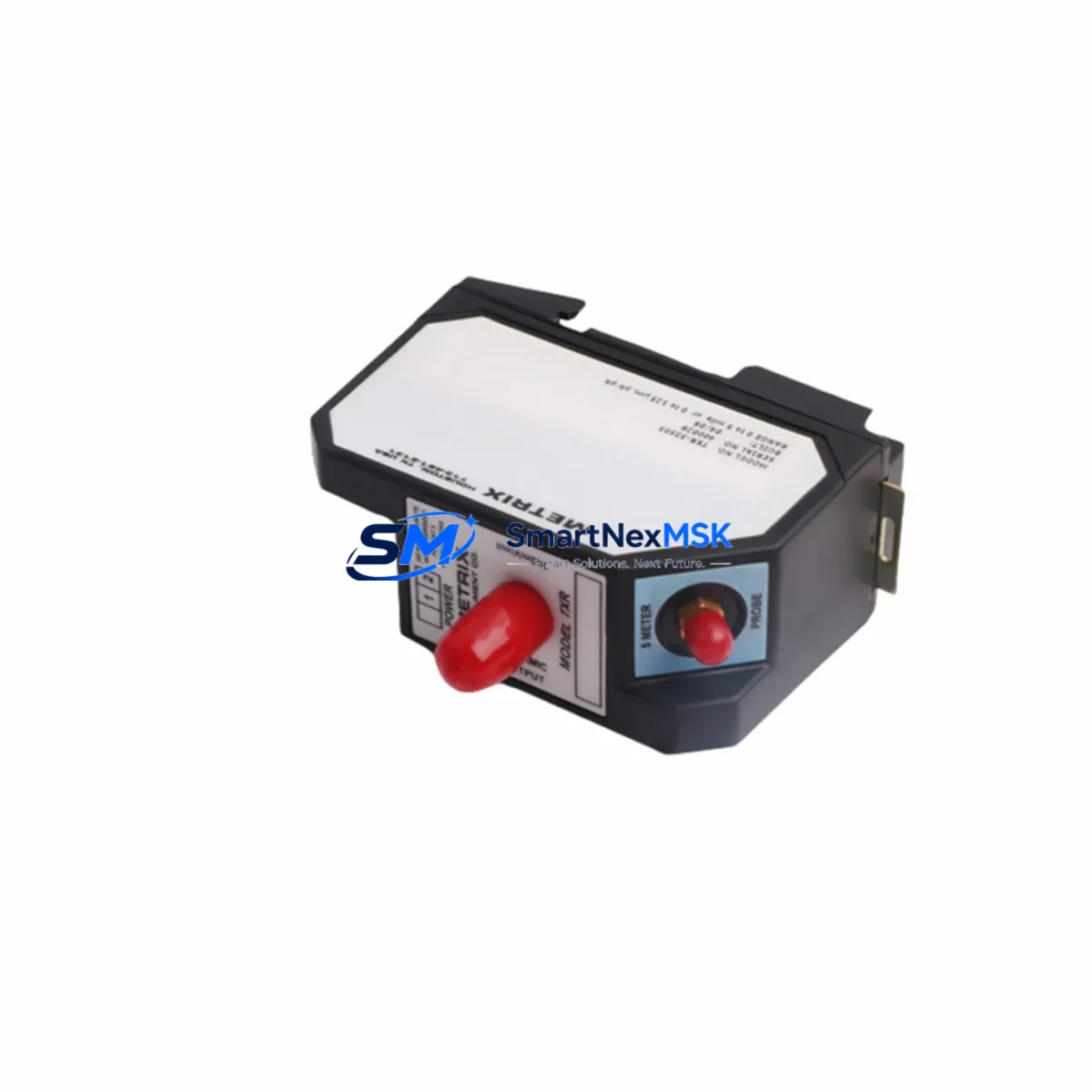
METRIX TXR-33505 Retrofit-Ready Vibration Transmitter for TXR Series Control Systems
The METRIX TXR-33505 is a loop-powered, 4–20 mA vibration transmitter engineered for seamless integration into existing TXR Series machinery protection and condition monitoring systems. Designed with retrofit compatibility as a core requirement, the TXR-33505 addresses the growing demand for drop-in replacements in aging industrial installations where the original transmitter has been discontinued, is no longer supported by the OEM, or has reached end-of-service life. Whether you are upgrading a turbine protection panel, modernizing a compressor monitoring rack, or restoring a legacy vibration monitoring loop, the TXR-33505 delivers the electrical and mechanical compatibility needed to minimize engineering rework and reduce total downtime.
SMARTNEXMSK maintains verified stock of the TXR-33505 and ships with full functional test documentation, making it a reliable source for both emergency replacement and planned maintenance programs. All units are covered by a 12-month warranty from date of shipment.
Upgrade Compatibility Table
| Parameter | TXR-33505 Specification | Retrofit Notes |
|---|---|---|
| Output Signal | 4–20 mA, 2-wire loop-powered | Compatible with existing DCS/PLC analog input cards; no signal conditioner required |
| Measurement Range | Velocity / Vibration (TXR Series standard) | Verify engineering unit scaling in DCS tag configuration before commissioning |
| Supply Voltage | 18–30 VDC (loop-powered) | Confirm loop supply voltage at terminal block; most legacy 24 VDC panels are compatible |
| Connector / Termination | Standard 2-pin terminal or M12 connector (model-dependent) | Match existing cable termination; adapter cables available for M12-to-terminal conversions |
| Mounting | Standard METRIX TXR Series mounting footprint | Direct bolt-on replacement; no bracket modification required for standard installations |
| Communication Protocol | Analog 4–20 mA (HART optional on select variants) | For HART-enabled systems, confirm HART revision compatibility with existing field communicator |
| Replacement Compatibility | Direct replacement for discontinued TXR Series transmitters | Cross-reference original tag number and cable color code before wiring |
| Commissioning Requirement | Zero/span verification at loop level | Use HART communicator or DCS faceplate to confirm 4 mA (zero) and 20 mA (full-scale) output |
| Warranty | 12 Months from shipment date | Covered by SMARTNEXMSK warranty; includes functional test report |
Retrofit Planning for Existing Automation Systems
A successful TXR-33505 retrofit begins well before the unit arrives on site. Engineers should start by auditing the existing vibration monitoring loop: confirm the loop supply voltage at the field junction box, verify the terminal block wiring diagram against the original METRIX installation drawing, and document the current 4–20 mA signal range as configured in the DCS or safety system analog input card. In many legacy installations, the vibration transmitter loop feeds directly into a Bently Nevada 3500 Series rack or a METRIX MX2033 signal conditioner, both of which accept standard 4–20 mA inputs and require no modification when the TXR-33505 is installed as a direct replacement.
For plants running Emerson DeltaV or Honeywell Experion PKS as the primary DCS, the analog input channel associated with the original transmitter tag should be placed in manual mode during the swap to prevent spurious alarms or protective trips. The I/O module — typically a DeltaV MD Plus Controller AI card or an Experion C300 analog input module — should be verified for loop impedance compatibility before the new transmitter is energized. In Yokogawa CENTUM VP installations, the FIO (Field I/O) node serving the vibration loop should similarly be confirmed for 4–20 mA passive input configuration.
Where the original installation used a METRIX ST5484E or ST5491E series transmitter in an adjacent channel on the same junction box, the TXR-33505 can be installed in parallel without disturbing the neighboring loop. Engineers should also confirm that the existing shielded cable — typically a Belden 8760 or equivalent twisted-pair — is intact and that the shield drain is grounded at one end only to avoid ground loops. If the cable run exceeds 300 meters, verify that the loop resistance budget (cable + input impedance) remains within the 4–20 mA driver’s compliance voltage specification.
For installations where the vibration transmitter feeds a Triconex TMR safety controller or an ICS Triplex AADvance safety system, the replacement procedure must follow the site’s Management of Change (MOC) process. The analog input channel should be bypassed in the safety logic before the transmitter is removed, and the bypass must be formally documented and approved. After installation of the TXR-33505, a full loop check — including simulation of 4 mA, 12 mA, and 20 mA signals using a Fluke 789 ProcessMeter or equivalent — must be completed and witnessed before the bypass is lifted.
In control cabinet upgrades where the original METRIX transmitter was mounted on a DIN rail alongside a Phoenix Contact MACX MCR signal conditioner or a Pepperl+Fuchs KFD2-STC4 isolating barrier, the TXR-33505 can be installed without replacing the associated signal conditioning hardware, provided the barrier’s input impedance and supply voltage remain within specification. This is a common scenario in older petrochemical and power generation installations where the field wiring and cabinet infrastructure are retained while only the sensing element is replaced.
Downtime Control During System Migration
Minimizing unplanned downtime is the primary operational concern when replacing a vibration transmitter in a running plant. The recommended approach is to pre-stage the TXR-33505 on the bench before the maintenance window: verify the unit powers up correctly on a 24 VDC bench supply, confirm the output reads 4 mA at rest, and document the serial number and functional test result. This pre-commissioning step eliminates the risk of discovering a configuration issue during the live swap.
During the actual replacement, the sequence should be: (1) notify the control room to acknowledge and suppress the associated vibration alarm in the DCS or historian; (2) isolate the loop at the field junction box using the existing loop disconnect or by opening the fuse holder; (3) remove the original transmitter and install the TXR-33505, reusing the existing cable terminations where possible; (4) re-energize the loop and confirm the DCS analog input reads a valid 4–20 mA signal; (5) perform a bump test or signal simulation to verify the full measurement range; (6) restore the alarm to active status and document the completion in the maintenance management system.
For critical machinery protection applications — such as turbine shaft vibration or compressor bearing temperature monitoring — the replacement should be coordinated with the machinery protection system vendor to ensure that the new transmitter’s response time and output characteristics are consistent with the original trip and alarm setpoints. If the plant uses a Bently Nevada System 1 software platform for online machinery diagnostics, the transmitter tag should be updated in the System 1 database to reflect the new serial number and calibration date. This preserves the integrity of the historical vibration trend data and ensures that the predictive maintenance program remains uninterrupted.
SMARTNEXMSK ships the TXR-33505 with a functional test report and, upon request, can provide a certificate of conformance to support the site’s MOC documentation package. Standard lead time from confirmed order to shipment is 3–5 business days for in-stock units, with express shipping available to minimize the gap between order placement and site delivery.
Retrofit Support FAQ
Q1: Is the TXR-33505 a direct drop-in replacement for the original METRIX TXR Series transmitter?
In the majority of installations, yes. The TXR-33505 shares the same mounting footprint, 2-wire loop-powered architecture, and 4–20 mA output as the original TXR Series transmitters. Before installation, verify the supply voltage, terminal wiring, and cable connector type against the original installation drawing. If the original unit used a non-standard connector or a custom cable assembly, contact SMARTNEXMSK for adapter options.
Q2: What commissioning steps are required after installing the TXR-33505?
After wiring, energize the loop and confirm the DCS or safety system analog input reads a valid signal (4 mA at rest for a zero-vibration condition). Perform a signal simulation using a calibrated loop calibrator to verify the 4 mA and 20 mA endpoints. If the system uses HART communication, connect a HART field communicator to confirm device identification and tag assignment. Document all commissioning results in the site maintenance record.
Q3: Can the TXR-33505 be used with existing signal conditioning hardware such as isolating barriers or signal conditioners?
Yes. The TXR-33505 is compatible with standard 4–20 mA isolating barriers (e.g., Pepperl+Fuchs KFD2 series, MTL 787+ series) and signal conditioners (e.g., Phoenix Contact MACX MCR series) commonly used in legacy installations. Verify that the barrier or conditioner’s input impedance and supply voltage are within the TXR-33505’s loop compliance specification before energizing.
Q4: What does the 12-month warranty cover, and what documentation is provided with shipment?
The 12-month warranty covers manufacturing defects and functional failures under normal operating conditions from the date of shipment. Each unit ships with a functional test report confirming 4 mA and 20 mA output verification. A certificate of conformance is available upon request to support MOC and quality documentation requirements. For warranty claims, contact SMARTNEXMSK at [email protected] with the unit serial number and a description of the fault.
© 2026 SMARTNEXMSK. All rights reserved.
Original Source: https://smartnexmsk.com
Contact: [email protected] | +86 18259474341