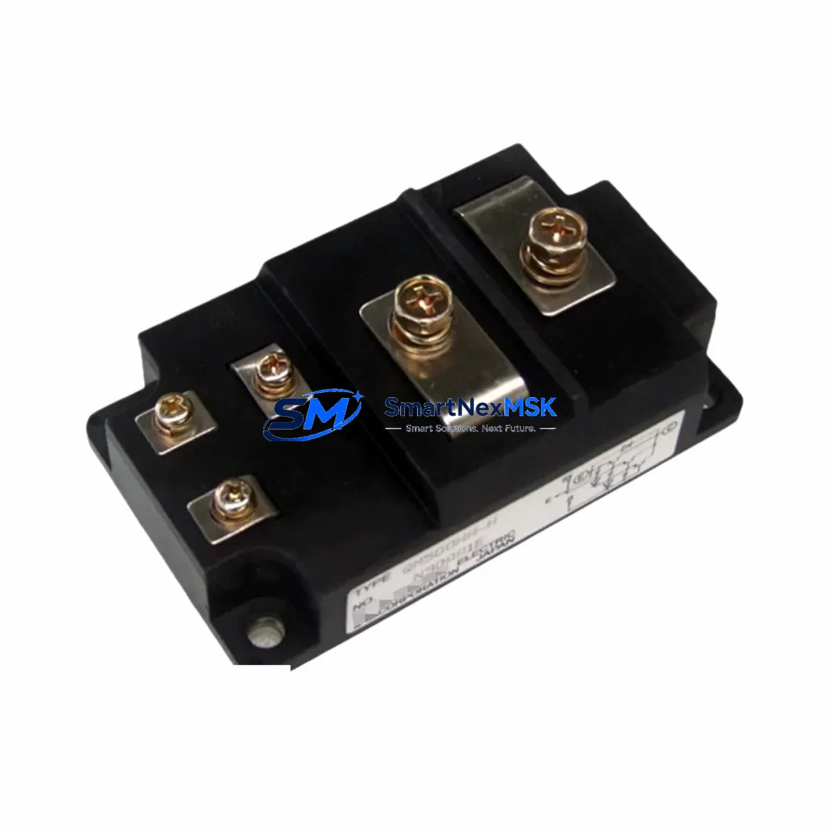
Mitsubishi CM110YE4-12F Retrofit-Ready Servo Relay for MR-J Series Control Systems
The Mitsubishi CM110YE4-12F is a retrofit-ready servo relay module engineered for seamless integration into legacy Mitsubishi MR-J Series servo drive systems. As production lines age and original components reach end-of-life, the CM110YE4-12F provides a verified, drop-in replacement path that preserves existing wiring layouts, terminal assignments, and control logic — minimizing engineering rework and unplanned downtime during system modernization.
Whether you are upgrading a standalone servo axis, retrofitting a multi-axis motion control cabinet, or restoring a discontinued spare in an emergency breakdown scenario, the CM110YE4-12F delivers the electrical and mechanical compatibility required for a smooth transition. This module is fully tested prior to shipment, backed by a 12-month warranty, and available from verified stock for immediate dispatch.
Upgrade Compatibility Table
| Parameter | CM110YE4-12F Specification | Retrofit Notes |
|---|---|---|
| Compatible Series | Mitsubishi MR-J Series (MR-J2, MR-J2S, MR-J3) | Verify drive generation before installation |
| Module Type | Servo Relay Module | Direct replacement for original relay assembly |
| Terminal Interface | Standard screw-terminal block | Confirm terminal pitch matches existing wiring harness |
| Mounting | DIN rail / panel mount | No bracket modification required for standard cabinets |
| Communication Compatibility | Compatible with SSCNET and analog command interfaces | Verify SSCNET cable routing if upgrading from MR-J2 to MR-J3 |
| Power Supply | 24 VDC control circuit | Confirm existing PSU capacity before adding relay load |
| Replacement Recommendation | Drop-in for discontinued OEM relay assemblies | Cross-reference original part number with supplier datasheet |
| Commissioning | Parameter initialization via MR Configurator2 | Back up existing servo parameters before replacement |
| Warranty | 12-Month Warranty — covers manufacturing defects; full pre-shipment functional test included | |
Retrofit Planning for Existing Automation Systems
Successful integration of the CM110YE4-12F into an existing MR-J Series installation requires a structured pre-replacement audit. Begin by documenting the current servo drive configuration, including the MR-J2S-□A or MR-J3-□A amplifier model, the associated encoder feedback cable type, and the CN1 connector wiring for the I/O interface. If the control cabinet also houses an MR-J3-D05 safety relay unit or an MR-BT0 battery backup module, confirm that these auxiliary components remain compatible with the replacement relay assembly.
For multi-axis systems running on a shared SSCNET III/H fiber optic network, verify that the relay module replacement does not interrupt the daisy-chain communication topology. Systems using a Mitsubishi Q-Series or iQ-R Series PLC as the motion controller — typically via a QD75MH or RD77MS positioning module — should have their axis parameters exported from GX Works3 before any hardware swap. This ensures that servo gain settings, electronic gear ratios, and in-position window values are preserved and can be reloaded after commissioning.
Terminal wiring adaptation is a critical step. The CM110YE4-12F uses a standard screw-terminal layout consistent with the MR-J Series relay interface. However, if the original installation used a CN3 terminal block adapter or a custom wiring harness for the electromagnetic brake output (pins RA1/RA2), these connections must be verified against the replacement module’s pinout diagram. In cabinets where an MR-J3-A-RJ004 option card or a CC-Link IE Field communication module is installed, confirm that the relay switching logic does not conflict with the fieldbus I/O mapping already configured in the PLC program.
Power budget verification is equally important. The 24 VDC control circuit supplying the relay coil must have sufficient residual capacity after accounting for all connected I/O modules, HMI panels, and safety relays in the cabinet. If the existing Mitsubishi PS-15 or PS-30 power supply module is operating near its rated output, consider adding a dedicated 24 VDC branch circuit for the relay assembly to prevent voltage sag during coil energization.
Downtime Control During System Migration
Minimizing production interruption during a servo relay replacement requires advance preparation and a disciplined changeover sequence. Before scheduling the maintenance window, use MR Configurator2 to export the full servo parameter set from the existing MR-J amplifier. Store this backup on a dedicated engineering laptop or USB drive that will be available on-site during the swap. If the machine is controlled by a GOT2000 Series HMI, export the screen project and alarm history as well, so that any HMI-side servo status displays can be verified after the replacement is complete.
During the physical swap, label all terminal connections before disconnecting the original relay module. Photograph the wiring layout from multiple angles. Disconnect the 24 VDC control power before removing the module, and verify with a multimeter that the circuit is de-energized. Install the CM110YE4-12F, reconnect all terminals in sequence, and restore control power. Perform a static check — confirm relay coil continuity and contact resistance — before enabling the servo amplifier.
On first power-up, initialize the servo parameters by reloading the saved configuration via MR Configurator2. Run the servo in test mode (JOG operation) at reduced speed before returning the axis to automatic operation. Verify encoder feedback signal integrity using the built-in diagnostic display on the MR-J amplifier. Confirm that the PLC program receives the correct ready signal from the servo drive before releasing the machine to production. This structured approach typically allows a single-axis relay replacement to be completed within a planned two-hour maintenance window, preserving control continuity and protecting the original program logic.
Retrofit Support FAQ
Q1: Is the CM110YE4-12F a direct drop-in replacement for the original Mitsubishi MR-J Series relay assembly?
A: Yes, the CM110YE4-12F is designed as a form-fit-function replacement for the original relay module used in MR-J2 and MR-J3 Series servo drive systems. Terminal layout, mounting dimensions, and coil voltage are consistent with the OEM specification. Minor wiring verification is recommended for installations that used custom harness adapters.
Q2: What commissioning steps are required after installing the CM110YE4-12F?
A: After physical installation, reload the servo parameter backup via MR Configurator2, verify encoder feedback signal quality, and run a JOG test at reduced speed before returning to automatic operation. If the system uses a SSCNET III/H network, confirm that the axis communication link is re-established and that the PLC motion program receives the correct servo-ready status before enabling automatic cycles.
Q3: How do I verify wiring compatibility before installation?
A: Cross-reference the CM110YE4-12F terminal pinout diagram against the existing CN1 and CN3 wiring records for your MR-J amplifier. Pay particular attention to the electromagnetic brake output terminals (RA1/RA2), the alarm output relay contacts, and the 24 VDC control power input. If original wiring records are unavailable, trace and document all connections before removing the original module.
Q4: What does the 12-month warranty cover, and is pre-shipment testing included?
A: Every CM110YE4-12F unit undergoes a full functional test prior to shipment, verifying coil resistance, contact continuity, and switching performance. The 12-month warranty covers manufacturing defects and functional failures under normal operating conditions. Units are shipped with a test record. For warranty claims, contact [email protected] with your order reference and a description of the fault.
© 2026 SMARTNEXMSK. All rights reserved.
Original Source: https://smartnexmsk.com
Contact: [email protected] | +86 18259474341