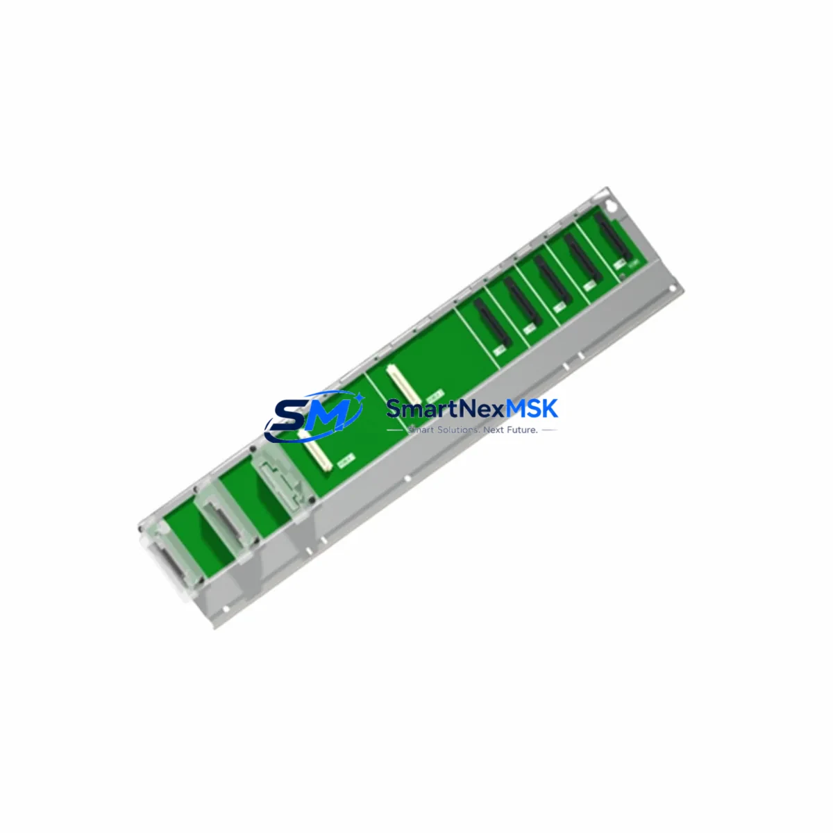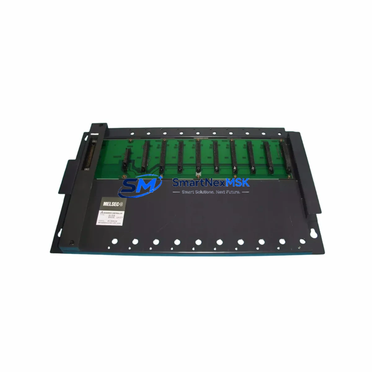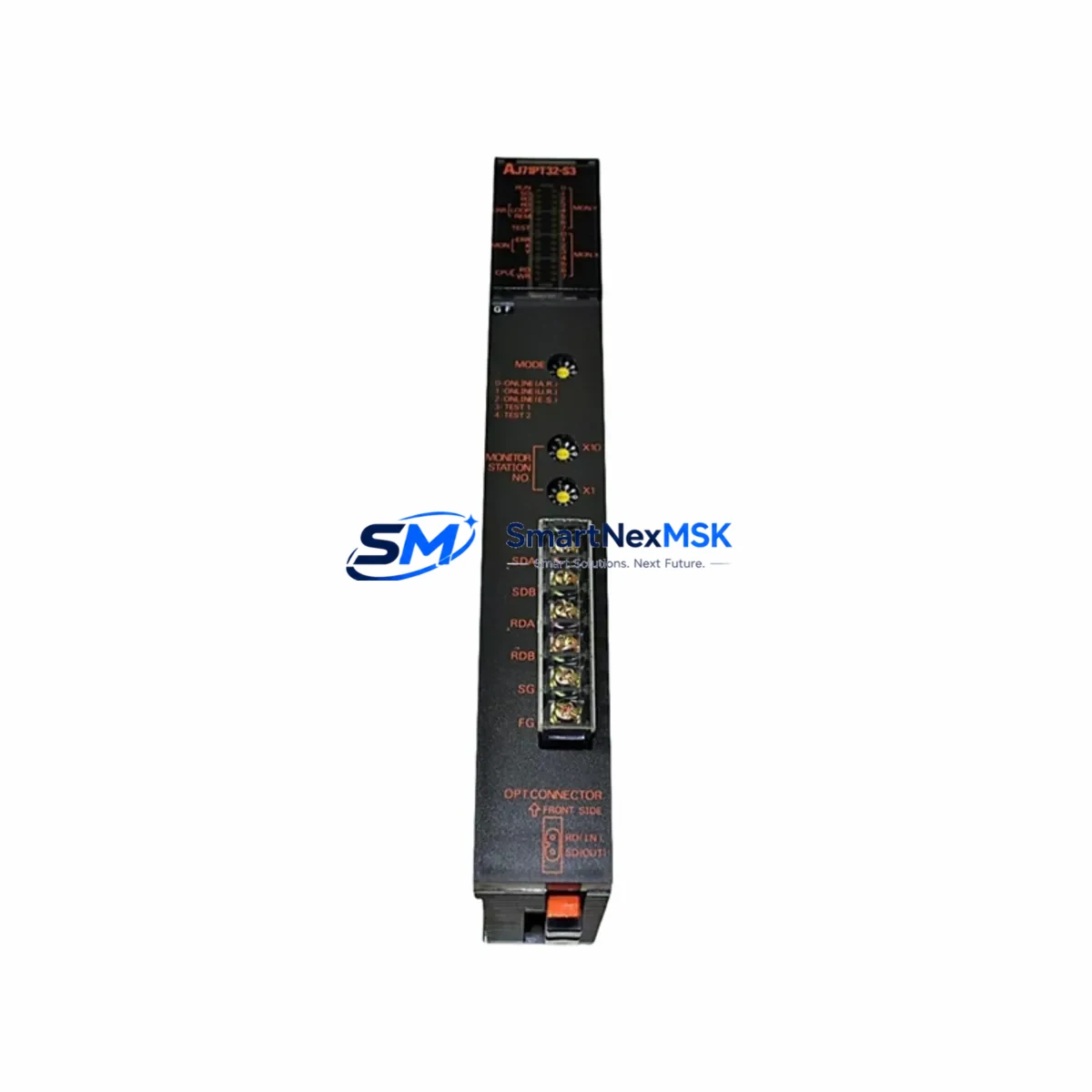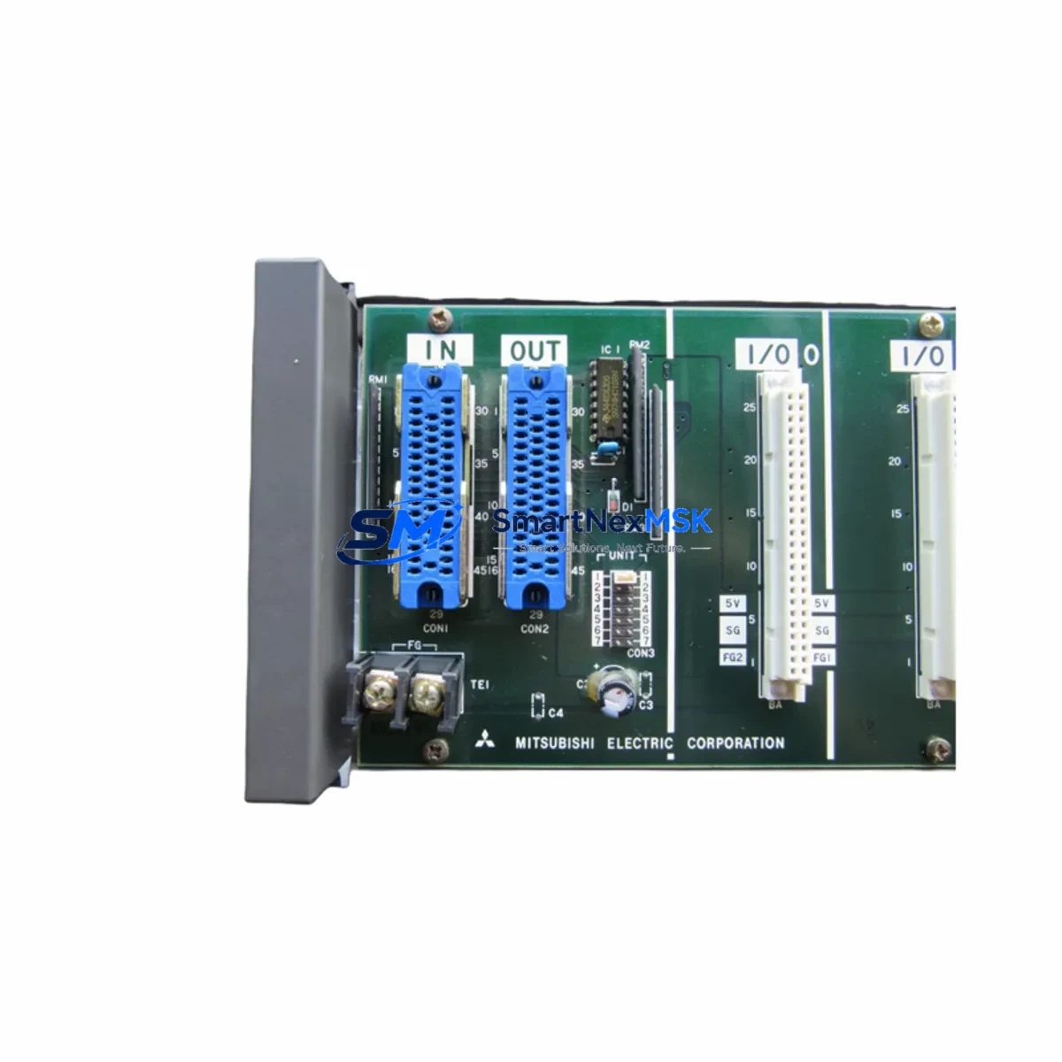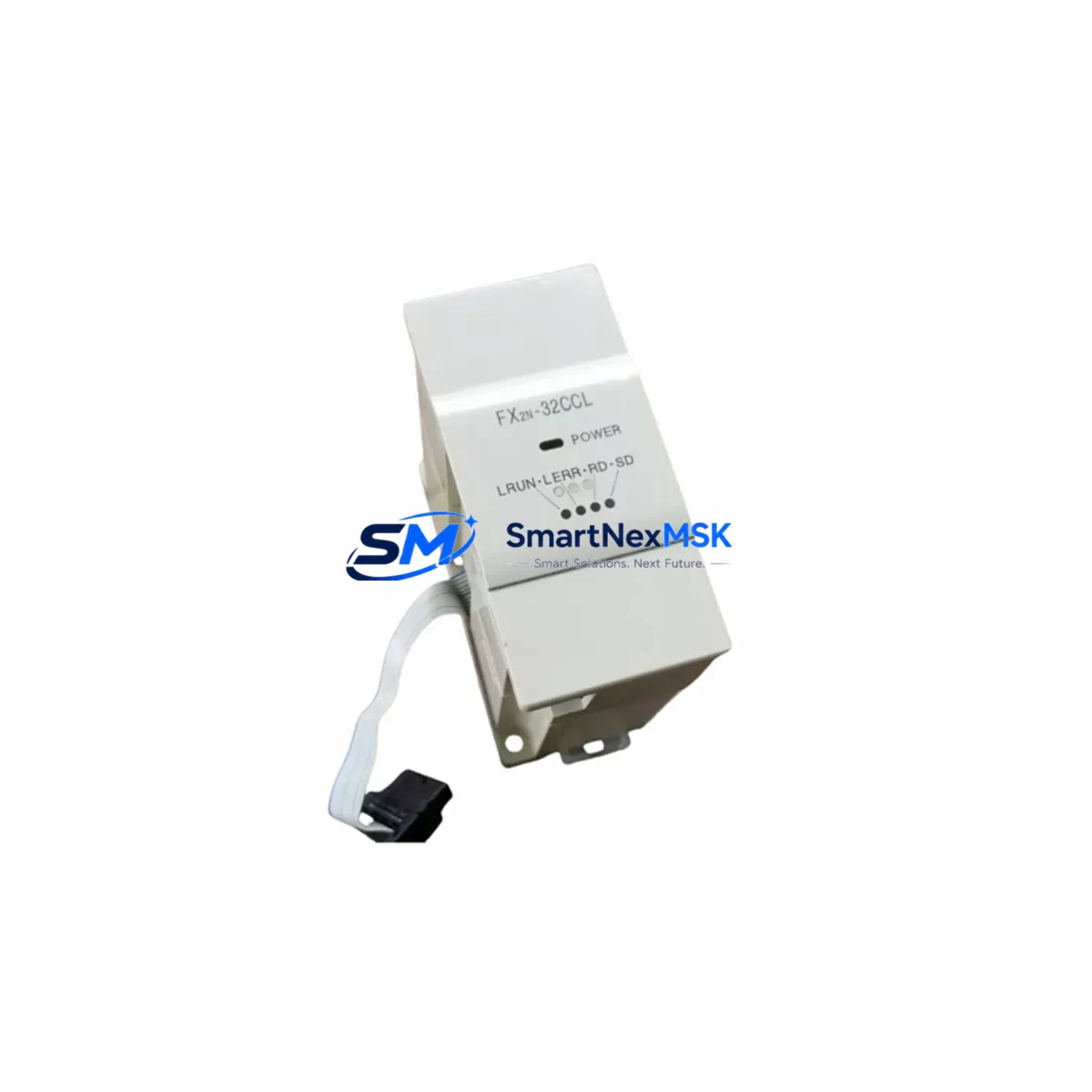
Mitsubishi FX2N-32CCL Retrofit-Ready CC-Link Module: Compatible Upgrade for Legacy MELSEC FX2N Control Systems
The Mitsubishi FX2N-32CCL is a CC-Link remote device station module designed for seamless integration into MELSEC FX2N series programmable logic controller systems. As legacy FX2N-based production lines reach end-of-life support cycles, the FX2N-32CCL remains one of the most sought-after retrofit components for engineers tasked with modernizing control cabinets without full system replacement. Whether you are restoring a discontinued spare, upgrading communication infrastructure, or migrating from an older CC-Link Gen 1 topology, this module provides a verified drop-in solution backed by a 12-month warranty and pre-shipment functional testing.
Industrial facilities running MELSEC FX2N PLCs frequently encounter the challenge of sourcing compatible communication modules when the original hardware fails or when expanding I/O capacity across distributed control nodes. The FX2N-32CCL supports up to 32 points of CC-Link remote I/O, making it suitable for applications involving conveyor control, packaging lines, press automation, and multi-axis motion coordination where reliable fieldbus communication is critical to maintaining production continuity.
Upgrade Compatibility Table
| Parameter | FX2N-32CCL Specification | Retrofit Notes |
|---|---|---|
| Compatible PLC Series | MELSEC FX2N, FX2NC | Verify FX2N main unit firmware version before installation |
| CC-Link Version | CC-Link Ver. 1.10 | Confirm master station supports Ver. 1.10; upgrade master if running Ver. 1.00 only |
| Remote I/O Points | 32 points (RX/RY) | Map remote I/O addresses in GX Developer or GX Works2 before commissioning |
| Communication Speed | 156 kbps – 10 Mbps | Match baud rate setting with existing CC-Link master (e.g., QJ61BT11N or AJ65BT-R2N) |
| Power Supply | 5 VDC via FX2N expansion bus | Verify FX2N base unit power budget; total expansion current must not exceed rated capacity |
| Installation Interface | FX2N right-side expansion connector | No additional backplane required; direct snap-on to FX2N main unit or FX2N-CNV-BD adapter |
| Station Type | Remote device station | Set station number via rotary switch; avoid duplicate addresses on the same CC-Link network |
| Replacement Compatibility | Direct replacement for original FX2N-32CCL | No program modification required if station address and baud rate match original configuration |
| Commissioning Tool | GX Developer / GX Works2 | Use CC-Link diagnostics in GX Works2 to verify link scan and remote station status |
| Warranty | 12 Months | Covers manufacturing defects; includes pre-shipment functional test report |
Retrofit Planning for Existing Automation Systems
A successful FX2N-32CCL retrofit begins well before the module arrives on-site. Engineers should start by auditing the existing control cabinet to document the current FX2N expansion configuration. In a typical MELSEC FX2N installation, the main CPU unit — such as the FX2N-64MR or FX2N-128MT — is flanked by a combination of analog input modules like the FX2N-4AD, analog output modules such as the FX2N-4DA, and digital I/O expansion blocks. The FX2N-32CCL occupies one expansion slot on the right side of the FX2N base unit and draws power directly from the internal 5 VDC bus, so confirming the remaining power budget across all connected expansion modules is a mandatory pre-installation step.
For facilities that also operate FX2N-232IF or FX2N-485BD communication boards for serial device connectivity, care must be taken to ensure that adding the FX2N-32CCL does not push the total expansion current beyond the FX2N main unit’s rated output. In cases where the power margin is tight, replacing an older FX2N-1PG pulse generator module or consolidating redundant I/O blocks can free up sufficient headroom for the CC-Link module without requiring a new power supply unit.
When the CC-Link network includes a master station based on a Q-series PLC — for example, a Q02UCPU paired with a QJ61BT11N CC-Link master module — the FX2N-32CCL must be registered as a remote device station in the network parameter settings within GX Works2. The station number is set physically via the rotary switch on the module face and must match the address reserved in the master’s CC-Link configuration. Duplicate station numbers are a common commissioning error that causes link scan failures and must be verified before powering up the network.
In retrofit scenarios involving older AJ-series or A-series master stations using AJ65BT-R2N remote terminal units, protocol compatibility should be confirmed at the CC-Link version level. The FX2N-32CCL operates under CC-Link Ver. 1.10, and while it maintains backward compatibility with Ver. 1.00 masters in most configurations, engineers should validate this against the master station’s hardware manual. If the existing master only supports Ver. 1.00, a firmware update or master module replacement — such as upgrading to a QJ61BT11N — may be required to unlock full functionality.
Terminal wiring for the CC-Link bus follows the standard three-wire configuration: DA, DB, and DG (shield ground). When replacing a failed FX2N-32CCL in an active production environment, photograph the existing wiring before disconnection and verify that the cable termination resistors (typically 110 Ω for CC-Link) are correctly positioned at both ends of the bus. Incorrect termination is a frequent cause of intermittent communication errors after module replacement.
Downtime Control During System Migration
Minimizing unplanned downtime during a CC-Link module replacement requires a structured approach that protects the existing PLC program logic and preserves field control continuity. Before removing the failed FX2N-32CCL, use GX Developer or GX Works2 to upload and save the complete FX2N program, including all device comments, parameter files, and network configuration data. Store this backup on a dedicated engineering laptop and verify the file integrity before proceeding.
If the production line cannot be taken fully offline, consider placing the CC-Link master station into test mode to isolate the affected remote station while keeping other network nodes operational. This approach is particularly effective in multi-drop CC-Link topologies where the FX2N-32CCL serves a non-critical auxiliary function such as status monitoring or auxiliary conveyor control, allowing the primary process to continue running during the swap.
After installing the replacement FX2N-32CCL, power up the FX2N system and use the CC-Link diagnostics function in GX Works2 to confirm that the new module is recognized as an active remote device station. Check the RX/RY link device mapping against the original program to ensure that all remote I/O addresses are correctly assigned. If the HMI — for example, a GOT2000 series GT2107 or GT2715 panel — displays any CC-Link communication error codes, use the GOT’s system monitor to identify the affected station and clear the error after confirming the link is stable.
For facilities with strict change management requirements, document the replacement with a pre/post commissioning checklist that records the module serial number, station address setting, baud rate configuration, link scan time, and the results of a 30-minute continuous operation test before returning the line to full production. This documentation also supports the 12-month warranty claim process in the event of a subsequent module failure.
Retrofit Support FAQ
Q1: Is the FX2N-32CCL a direct drop-in replacement for a failed unit without program changes?
In most cases, yes. If the replacement module is configured with the same station number and baud rate as the original, the FX2N PLC program does not require modification. The CC-Link master will recognize the new module at the same network address and resume normal link scan operation. However, if the original module’s station address is unknown, you will need to read the network parameter settings from the FX2N program backup to determine the correct configuration before installation.
Q2: What wiring checks should be performed before powering up the replacement module?
Verify that the DA, DB, and DG terminals are connected in the correct polarity and that the CC-Link cable shield is grounded at one end only to prevent ground loops. Confirm that the 110 Ω termination resistors are installed at both physical ends of the CC-Link bus. Check that the FX2N expansion connector is fully seated and that no bent pins are present on the interface. Finally, measure the 5 VDC supply voltage at the expansion bus to confirm it is within the specified tolerance before enabling the CC-Link link scan.
Q3: How is the FX2N-32CCL tested before shipment, and what does the 12-month warranty cover?
Each FX2N-32CCL unit undergoes a pre-shipment functional test that verifies CC-Link communication link establishment, remote I/O point operation, and power consumption within specification. The 12-month warranty covers manufacturing defects and functional failures under normal operating conditions. It does not cover damage caused by incorrect wiring, overvoltage, physical impact, or installation in environments outside the module’s rated temperature and humidity range. A test report is available upon request.
Q4: Can the FX2N-32CCL be used in a system that is being migrated from FX2N to iQ-F or iQ-R series PLCs?
The FX2N-32CCL is designed specifically for the FX2N expansion bus and is not directly compatible with iQ-F (FX5U/FX5UC) or iQ-R series main units, which use different expansion interfaces. For migration projects, the CC-Link remote I/O function can be replicated using iQ-F compatible modules such as the FX5-CCL-MS CC-Link master/local module, which supports the same CC-Link Ver. 1.10 network and allows existing remote device stations to remain in service during a phased controller upgrade. This approach preserves the field wiring and remote I/O configuration while replacing only the PLC CPU and expansion modules.
© 2026 SMARTNEXMSK. All rights reserved.
Original Source: https://smartnexmsk.com
Contact: [email protected] | +86 18259474341